Detection device for automatically fixing pressure regulating valve

A detection device and a pressure regulating valve technology, applied in the field of pressure regulating valves, can solve the problems of poor air tightness, inability to regulate the pressure of the valve core, wrong judgment, etc., and achieve the effects of accurate detection results and improved versatility

Inactive Publication Date: 2021-04-16
行唐县雄飞物业管理有限公司
View PDF9 Cites 1 Cited by
  • Summary
  • Abstract
  • Description
  • Claims
  • Application Information

AI Technical Summary

Benefits of technology

The technical effect of this patented technology allows for precise labeling of detected results from various types of regulators used on an engine's exhaust system. By pressing downward against a magnetized roller called a pressure sliding board, which moves along its surface, it can also be marked if there are any issues related to certain components or functions within the device. This ensures better accuracy compared to other methods such as color-coded indications. Additionally, when the valves have been installed correctly, they will move back into their original position after being checked again during maintenance work without interferring with them.

Problems solved by technology

The technical problem addressed in this patented text relates to manual testing for pressure regulators that can result in leaks when they have been partially worn out during their usage period. This could also happen if the valving mechanism fails causing excessive airflow through the system without being properly controlled by an external device like pumping water.

Method used


Image

  • Detection device for automatically fixing pressure regulating valve
  • Detection device for automatically fixing pressure regulating valve
  • Detection device for automatically fixing pressure regulating valve

Examples


Embodiment Construction

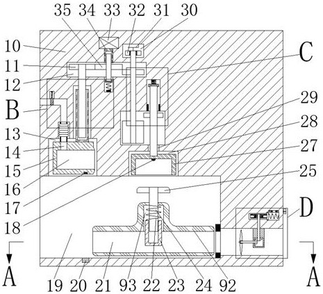
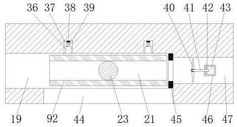
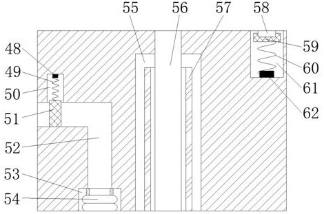
[0020] Combine below Figure 1-6 The present invention is described in detail, wherein, for the convenience of description, the orientations mentioned below are defined as follows: figure 1 The up, down, left, right, front and back directions of the projection relationship itself are the same.

[0021]A detection device for an automatic fixed pressure regulating valve described in conjunction with accompanying drawings 1-6 includes a detection box 10, and an exhaust chamber 47 with an opening to the right is provided in the detection box 10, and the upper side of the exhaust chamber 47 is A centrifugal cavity 75 is provided, and the right side of the centrifugal cavity 75 is communicated with a push plate cavity 84, and the upper side of the push plate cavity 84 is connected with a detection block cavity 87, and the right end wall of the detection block cavity 87 is rotated and connected with a Extending to the left to the left end wall of the detection block chamber 87 and exte


PUM


Abstract

The invention relates to the related field of pressure regulating valves, and discloses a detection device for automatically fixing a pressure regulating valve. The detection device comprises a detection box, the detection box is internally provided with an exhaust cavity with a rightward opening, the upper side of the exhaust cavity is provided with a centrifugal cavity, the right side of the centrifugal cavity is communicated with a push plate cavity, and the upper side of the push plate cavity is communicated with a detection block cavity. A threaded lead screw shaft extending leftwards into the left end wall of the detection block cavity and extending rightwards to the outside is connected into the right end wall of the detection block cavity in a rotating fit mode, a pressure push plate moves rightwards to make contact with a pressure sliding block in an abutting mode to send a marking magnetic block, and therefore the detection result of the pressure regulating valve block is marked. The air pressure transmission block pushes the pressure regulating valve block to abut against the sealing induction coil to ensure the sealing performance, so that the detection result is more accurate, and meanwhile, the valve body detection block is driven to move left and right by rotating the setting knob, and thus the detection standard intervals of different types of pressure regulating valve blocks are adjusted, and the universality of detection is improved.

Description


Claims


Application Information

Patent Timeline
Owner 行唐县雄飞物业管理有限公司
Why Eureka
Try Eureka