Antenna device and electronic equipment

A technology of antenna device and antenna module, which is applied in the direction of antenna support/mounting device, antenna, antenna parts, etc., can solve the problems of reduced working performance of electronic equipment and easy influence on communication of electronic products, and achieve the effect of improving the overall working performance

Pending Publication Date: 2021-04-30
LENOVO (BEIJING) CO LTD
View PDF21 Cites 0 Cited by
  • Summary
  • Abstract
  • Description
  • Claims
  • Application Information

AI Technical Summary

Problems solved by technology

[0002] When the antenna part of the electronic device is in the working state, it will generate a certain amount of electromagnetic wave energy. At this time, when the user is close to the electronic device for a certain distance, the corresponding electromagnetic wave energy will be absorbed and dissipated, that is, a certain bit absorption rate (

Method used


Image

  • Antenna device and electronic equipment
  • Antenna device and electronic equipment
  • Antenna device and electronic equipment

Examples


Embodiment Construction

[0042] The technical solutions in the embodiments of the present application will be clearly and completely described below in conjunction with the drawings in the embodiments of the present application.

[0043] It should be understood that the specific embodiments described here are only used to explain the present application, and are not intended to limit the present application.

[0044] With the development of thinner and lighter electronic devices, the SAR of electronic devices will easily exceed the standard while meeting the performance requirements of Over the Air (OTA) technology; for example: foldable notebook computers in notebook (NoteBook, NB) mode and tablet The SAR in the (Tablet) mode satisfies the requirements of the Federal Communications Commission (Federal Communications Commission, FCC) standard and at the same time the performance of the antenna is easily affected.

[0045] In related technologies, the following two schemes are usually used to make SAR mee


PUM


Abstract

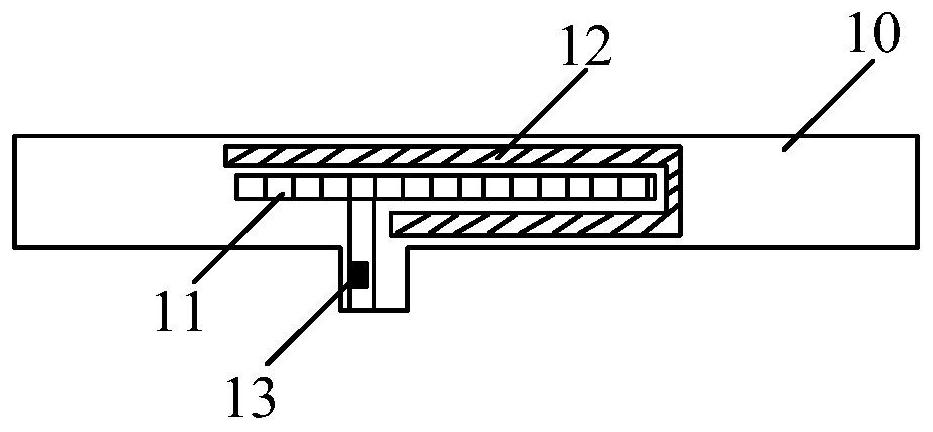
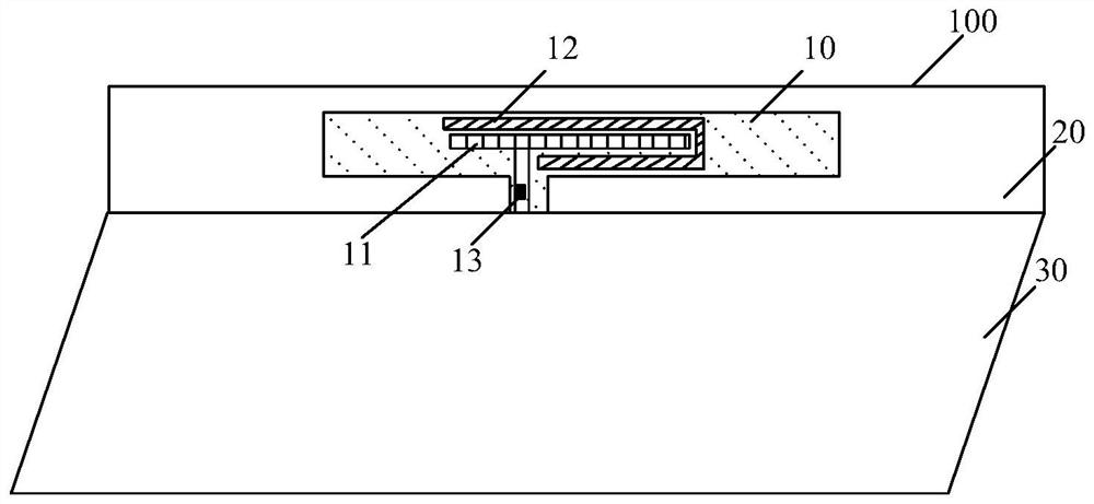
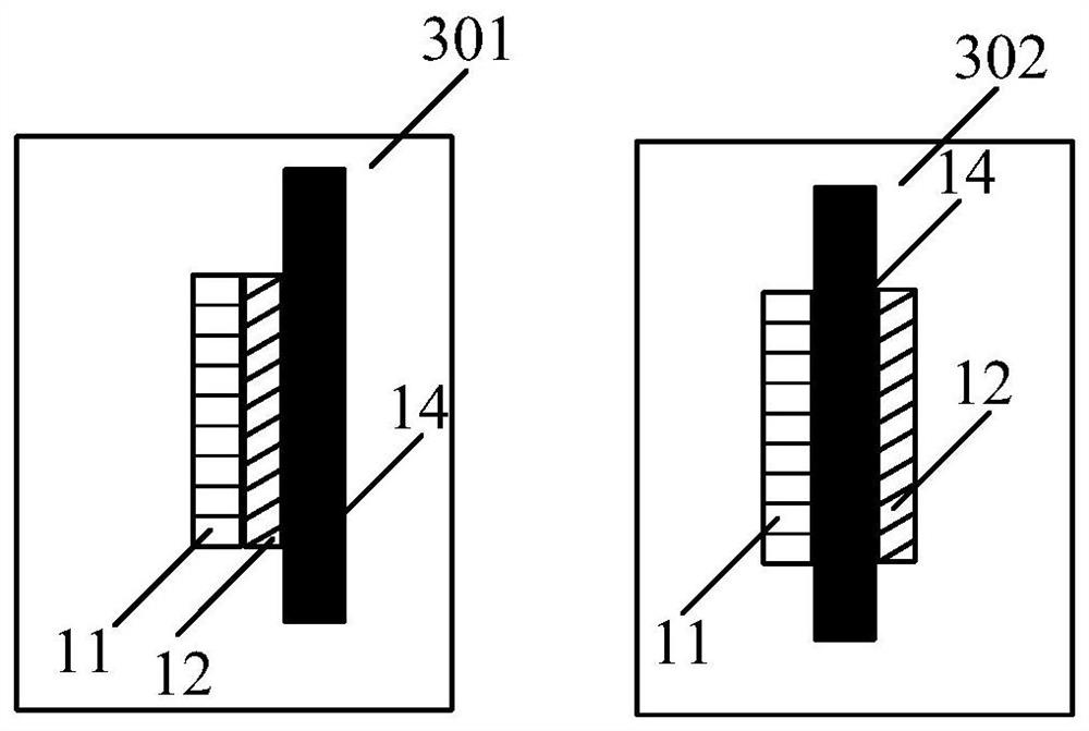
The embodiment of the invention discloses an antenna device. The antenna device comprises an antenna module which is disposed in a housing and is used for receiving and/or transmitting a radio frequency signal; a gap which is formed in the shell and at the periphery of the antenna module; a first detection module, which is arranged on the shell, wherein a preset distance is formed between the first detection module and the antenna module, and the antenna module and the first detection module are insulated, the first detection module being used for detecting the electromagnetic radiation quantity generated by the antenna module in a working state; a feed point which is arranged in the shell and is electrically connected with the antenna module; wherein the antenna module can couple the received and/or transmitted radio frequency signal to the first detection module. The embodiment of the invention further discloses electronic equipment.

Description


Claims


Application Information

Patent Timeline
Owner LENOVO (BEIJING) CO LTD
Why Eureka
Try Eureka