Antenna device and terminal

An antenna device and antenna technology, applied in the directions of antenna grounding device, antenna support/installation device, antenna, etc., can solve the problem that it is difficult to meet the three-frequency resonance of the antenna, and achieve the effect of reducing the demand for area and length

Active Publication Date: 2018-12-28
BLACKSHARK TECH NANCHANG CO LTD
View PDF9 Cites 0 Cited by
  • Summary
  • Abstract
  • Description
  • Claims
  • Application Information

AI Technical Summary

Benefits of technology

This patented technology allows multiple types of signals (GPS/Wi-FI) from different sources or devices to work together simultaneously with one another without adding extra components like an external signal source. It also integrates these three types of radios onto just one single piece of metal that forms part of the main housing of this system. Additionally, it includes a double cameras setup where both gpsotropic sensors and wireless communication equipment have been added separately. Overall, this design improves efficiency while minimizing space requirements compared to traditional systems.

Problems solved by technology

This patented technical problem addressed in this patents relates to how to improve the performance of an electronic device's wireless communication signal while also reducing its size without compromising their overall look or functionality.

Method used


Image

  • Antenna device and terminal
  • Antenna device and terminal
  • Antenna device and terminal

Examples


Embodiment Construction

[0024] The following will clearly and completely describe the technical solutions in the embodiments of the present invention with reference to the accompanying drawings in the embodiments of the present invention. Obviously, the described embodiments are only some, not all, embodiments of the present invention. Based on the embodiments of the present invention, all other embodiments obtained by persons of ordinary skill in the art without making creative efforts belong to the protection scope of the present invention.

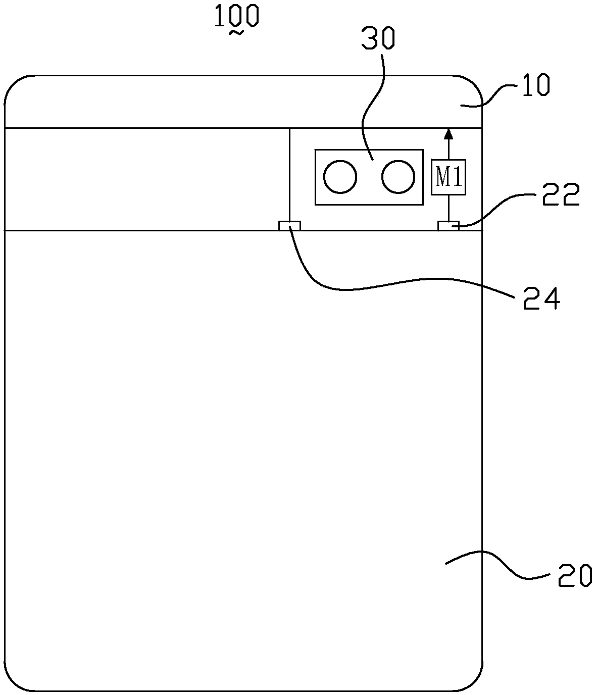
[0025] Please refer to figure 1 , figure 1 It is a schematic structural diagram of the antenna device provided by the first embodiment of the present invention. Such as figure 1 As shown, the antenna device 100 includes an antenna body 10 , a ground terminal 24 , a feed point 22 and a printed circuit board 20 . Specifically, in this embodiment, a matching circuit M1 is provided on the path of the feed point 22 . The feed point 22 is electrically connected to


PUM


Abstract

An antenna device includes an antenna body, a ground terminal, and a feed point. A matching circuit is arranged on the path of the feed point, the feed point is electrically connected to the antenna body via the matching circuit, the ground terminal is electrically connected to the antenna body, and the ground terminal and the feed point are grounded via a printed circuit board. The invention alsoprovides a terminal. The antenna device and the terminal provided by the invention simultaneously realize the functions of the GPS antenna, WiFi-2.4G antenna and the WiFi-5G antenna by arranging a matching circuit at the feed point and can reduce the demand for antenna length.

Description


Claims


Application Information

Patent Timeline
Owner BLACKSHARK TECH NANCHANG CO LTD
Why Eureka
Try Eureka