LED lamp bead tinning mechanism

A technology of LED lamp bead and rotating mechanism, which is applied in the direction of assembling printed circuit with electrical components, glass production, etc. It can solve the problems of time-consuming and laborious tinning operation, large manual labor force, and incomplete tinning on circuit boards, etc., to reduce inconsistency sexual effect

Active Publication Date: 2021-06-04
绍兴微创电子科技有限公司
View PDF19 Cites 1 Cited by
  • Summary
  • Abstract
  • Description
  • Claims
  • Application Information

AI Technical Summary

Benefits of technology

This technology allows for quicker and more consistency when attaching multiple lamps together with an automatic clip mechanism that simplifies the process. It achieves this through two different ways - it uses circular or rectangular slots on both sides of the light bulbs' leads (LEDs) instead of just wires). When closed, there is no longer any extra steps needed because they only require manipulation from outside. Additionally, the system includes features like tensioners at either end to keep them securely attached during installation. Overall, these technical improvements make assembly easier and faster than traditional methods.

Problems solved by technology

This technical problem addressed by this patented technology relates to developing a new type of light source for use in electronic devices such as lights used in automobiles, tables, laptops, etc., without requiring manual work due to its high impact strength against external forces like vibrations caused from vehicles' movement during driving.

Method used


Image

  • LED lamp bead tinning mechanism
  • LED lamp bead tinning mechanism
  • LED lamp bead tinning mechanism

Examples


Embodiment

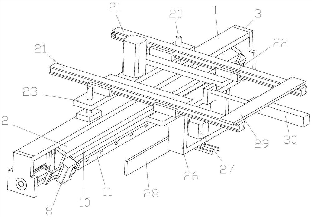
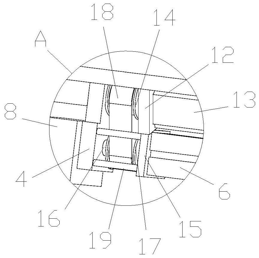
[0017] Embodiment: A tinning mechanism for LED lamp beads, such as Figure 1-Figure 3 As shown, it includes a rotating mechanism and a moving mechanism. The rotating mechanism includes an upper shelf plate 1 and a lower shelf plate 2. An outer mounting plate 3 is respectively connected to two ends of the upper shelf plate 1, and the two ends of the lower shelf plate 2 Each is connected with an inner mounting plate 4, and the inner surfaces of the two outer mounting plates 3 are rotatably connected with a rotating shaft 5 through a bearing. It is fixedly connected with the inner end of the rotating connecting column 6 on the left side, a left clamping cylinder 7 is provided on the inner side of the inner mounting plate 4 on the left side, and a right clamping cylinder 7 is arranged on the inner side of the inner mounting plate 4 on the right side. The cylinder 8, the left clamping cylinder 7 and the right clamping cylinder 8 can achieve the closing and opening of the mounting fram


PUM


Abstract

The invention discloses an LED lamp bead tinning mechanism, and belongs to the technical field of LED manufacturing equipment. Multiple LED lamp beads can be clamped at a time through arc grooves which are correspondingly formed, the non-uniformity of manual operation is greatly reduced, a left clamping air cylinder and a right clamping air cylinder can achieve closing and opening of a mounting frame plate, clamping of the LED lamp beads is achieved, a driving motor drives a first belt wheel to rotate, a second belt wheel is driven to rotate through a transmission belt, and due to the fact that a short shaft is fixedly connected with a second belt wheel, an inner mounting plate on the right side is fixedly connected with a connecting plate through the short shaft, the second belt wheel rotates to drive a mounting frame plate to rotate around the short shaft, the mounting frame plate is moved downwards through cooperation of a first air cylinder, and tinning of LED lamp beads and lamp bases can be achieved.

Description


Claims


Application Information

Patent Timeline
Owner 绍兴微创电子科技有限公司
Why Eureka
Try Eureka