Automatic chip mounter

An automatic placement machine and patch technology, which is applied in the assembly/disassembly of contacts, electrical components, electric switches, etc., can solve the problems of high labor demand and low degree of automation, and achieve the effect of high efficiency and rapid transfer

Pending Publication Date: 2021-06-18
青岛鑫圣林电子有限公司
View PDF0 Cites 0 Cited by
  • Summary
  • Abstract
  • Description
  • Claims
  • Application Information

AI Technical Summary

Benefits of technology

This invention relies about an apparatus for collecting materials such as rocks or plasterboards onto templates used during construction projects. It uses motors to move the tools around, allowing them to be quickly transferred between different positions without stopping at each step. By applying this technology, it can improve productivity and reduce costs associated therewith.

Problems solved by technology

This patented describes how current methods involve multiple steps in order to install shuttles into electronic devices with specific areas that require them. These processes are time-consuming and manual, making it difficult if done properly by human operators who have limited training hours. Additionally, there may be issues where incorrect installation can lead to performance degradations overtime due to poor alignment between different layers within these systems.

Method used


Image

  • Automatic chip mounter
  • Automatic chip mounter
  • Automatic chip mounter

Examples


Embodiment Construction

[0027] The following will clearly and completely describe the technical solutions in the embodiments of the present invention with reference to the accompanying drawings in the embodiments of the present invention. Obviously, the described embodiments are only some, not all, embodiments of the present invention. Based on the embodiments of the present invention, all other embodiments obtained by persons of ordinary skill in the art without making creative efforts belong to the protection scope of the present invention.

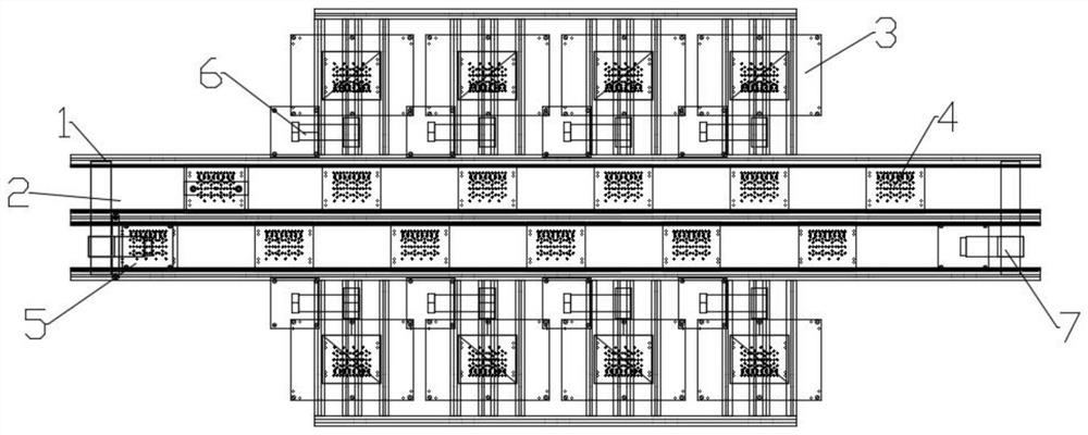
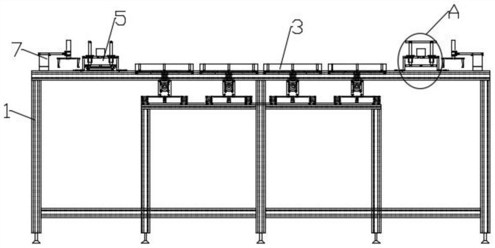
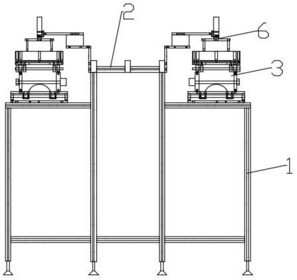
[0028] see Figure 1-8 , the present invention provides a technical solution: an automatic placement machine, including a frame 1, two conveyor belts 2 are installed in the middle of the frame 1, a plurality of swinging machines 3 are installed on both sides of the frame 1, and there are 3 swinging machines The first transfer hand 6 is installed on the frame 1, the template 4 is placed in the conveyor belt 2 and the swing machine 3, the placement mechanism 5 is i


PUM


Abstract

The invention discloses an automatic chip mounter. The chip mounter comprises a rack, wherein two conveying belts are installed in the middle of the rack, a plurality of wobbler machines are installed on two sides of the rack, first transfer hands are installed on the rack at the wobbler machines, templates are placed in the conveying belts and the wobbler machines, and a chip mounting mechanism is installed on the rack at one ends of the two conveying belts; and a second transfer hand is mounted on the rack at the chip mounting mechanism. Firstly, a template is placed into each wobbler, demagnetized elastic pieces are quantitatively poured into each wobbler, the wobbler swings in all directions so as to array the elastic pieces into the template, then a first transfer hand sucks the template onto a transfer belt, the transfer belt conveys the template with the elastic pieces to a chip mounting mechanism, then the empty template continues to be moved to the second transfer hand, and the second transfer hand transfers the empty template to another conveying belt, so the elastic sheet is adhered to the adhesive tape, automatic surface mounting is realized, and then the empty template is continuously moved to the second transfer hand.

Description


Claims


Application Information

Patent Timeline
Owner 青岛鑫圣林电子有限公司
Why Eureka
Try Eureka