Quasi-coherent pulse ultra-wideband receiver and signal demodulation method

An ultra-wideband receiver and coherent pulse technology, applied in electrical components, transmission systems, etc., can solve the problems of increasing system power consumption and difficulty in applying low-power application scenarios, and achieve the effect of strong resistance

Active Publication Date: 2021-06-25
TSINGHUA UNIV
View PDF6 Cites 0 Cited by
  • Summary
  • Abstract
  • Description
  • Claims
  • Application Information

AI Technical Summary

Problems solved by technology

Although the coherent pulse ultra-wideband receiver has strong resistance to non-ideal factors such as narrowband interference and multipath effects, it requires a high-precision

Method used


Image

  • Quasi-coherent pulse ultra-wideband receiver and signal demodulation method
  • Quasi-coherent pulse ultra-wideband receiver and signal demodulation method
  • Quasi-coherent pulse ultra-wideband receiver and signal demodulation method

Examples


Embodiment Construction

[0043] The following will clearly and completely describe the technical solutions in the embodiments of the present invention with reference to the accompanying drawings in the embodiments of the present invention. Obviously, the described embodiments are only some, not all, embodiments of the present invention. Based on the embodiments of the present invention, all other embodiments obtained by persons of ordinary skill in the art without making creative efforts belong to the protection scope of the present invention.

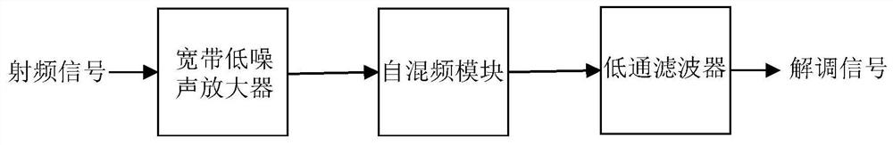
[0044] As mentioned in the Background Art, see figure 1 , the conventional incoherent pulse ultra-wideband receiver has a simple structure, the radio frequency signal is first amplified by a wideband low-noise amplifier, and the self-mixing module performs self-mixing operation on the amplified signal and sends the obtained signal to a low-pass filter. The second and above harmonic components are filtered out after passing through a low-pass filter, and the pulse


PUM


Abstract

The invention provides a quasi-coherent pulse ultra-wideband receiver. The received radio frequency signal is decomposed into two paths of orthogonal signals after being down-converted into low and intermediate frequencies; therefore, even if the quality of the radio frequency local oscillation signal is not high, the influence of the frequency error can be eliminated after the two paths of orthogonal signals are subjected to square addition; the demodulation performance of the quasi-coherent pulse ultra-wideband receiver is not sensitive to a phase error and a frequency error between a radio frequency signal and a radio frequency local oscillation signal. According to the invention, a high-quality radio frequency local oscillation signal is not needed, a high-precision frequency synthesizer and a high-speed analog-digital converter are not needed, and the equipment is suitable for a low-power-consumption application scene. In addition, the capability of resisting non-ideal factors such as narrow-band interference is high. The invention further provides a signal demodulation method which is applied to the quasi-coherent pulse ultra-wideband receiver.

Description


Claims


Application Information

Patent Timeline
Owner TSINGHUA UNIV
Why Eureka
Try Eureka