Mechanical lock

A technology for mechanical locks and front locks, which is applied to non-mechanical transmission-operated locks, building locks, and devices that prevent keys from being removed from the lock, which can solve problems such as hidden safety hazards and inability to unlock the lock.

Pending Publication Date: 2021-07-20
GUANGDONG JINDIAN ATOM LOCK
View PDF0 Cites 0 Cited by
  • Summary
  • Abstract
  • Description
  • Claims
  • Application Information

AI Technical Summary

Benefits of technology

This technology helps analyze an accidental locked door mechanism for better understanding when there's another problem happening during normal usage. By separating these parts into two separate areas: one works properly while the other doesn’t work well enough or even gets stuck due to factors like rusting from rainwater or snow falling onto them.

Problems solved by technology

In current full-automatic finger print loves available today there are two types: one uses motors and other parts like springs to achieve locking/unlocking; another design involves connecting the spring mechanism directly onto the back plate without any moving parts such as bolters. However, these designs have their own drawbacks - they may lead to unsafe conditions when inserting tools (such as keys) which could damage them if someone tries to break it off during operation.

Method used


Image

  • Mechanical lock
  • Mechanical lock
  • Mechanical lock

Examples


Embodiment Construction

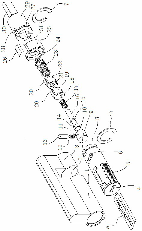
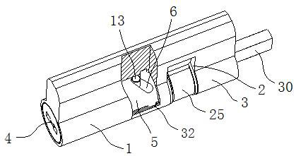
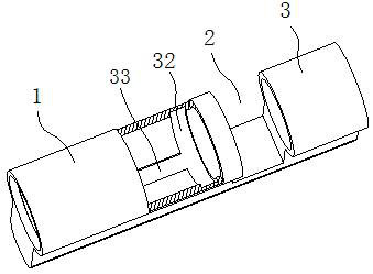
[0020] See figure 1 — Figure 4 , Image 6 , the mechanical lock head provided by the present invention includes a front lock tube 1 and a rear lock tube 3, an emergency lock cylinder 5 and a lock rod 30 arranged in the front lock tube 1 and the rear lock tube 3, and an emergency lock cylinder 5 and a lock rod 30 arranged in the front lock tube 1 and the rear lock tube The dial 25 connected to the emergency lock core 5 and the lock bar 30 through the clutch assembly between the lock tubes 3; the key slot 4 of the emergency lock core 5 is a blind hole, and the emergency lock core 5 and the clutch assembly A push block assembly is provided; the push block assembly includes a rotatable push block 10 arranged in the rear of the emergency lock cylinder 5 and a thrust column 13 arranged radially on the push block 10, and the push block 10 is provided with a spring hole 11 The thrust column 13 is movable in the spring hole 11, and the spring 12 is arranged between the thrust column 13


PUM


Abstract

The invention discloses a mechanical lock. The mechanical lock comprises a front lock tube, a rear lock tube, an emergency lock cylinder, a lock rod and a shifting wheel, wherein the emergency lock cylinder and the lock rod are arranged in the front lock tube and the rear lock tube; the shifting wheel is arranged between the front lock tube and the rear lock tube and connected with the emergency lock cylinder and the lock rod through a separation and reunion assembly; a key groove of the emergency lock cylinder is a blind hole; a push block assembly is arranged between the emergency lock cylinder and the separation and reunion assembly; the push block assembly comprises a push block movably arranged in the rear portion of the emergency lock cylinder and a thrust column arranged on the push block in the radial direction; an inclined groove matched with the thrust column is formed in the side wall of the rear portion of the emergency lock cylinder; and a straight sliding groove matched with the thrust column on the push block and an annular sliding groove located in the rear end of the straight sliding groove are formed in the inner wall of the front lock tube. According to the mechanical lock, the key groove is designed to be the blind hole in the emergency lock cylinder, and the separation and reunion assembly is isolated from the key groove, so that the problem that a motor assembly idles and cannot be unlocked due to the fact that the lock rod is in an idling state when a tool is inserted into the key groove to push the separation and reunion assembly is fundamentally solved.

Description


Claims


Application Information

Patent Timeline
Owner GUANGDONG JINDIAN ATOM LOCK
Why Eureka
Try Eureka