Charging and discharging current control method of parallel battery energy storage system

A battery energy storage system, charging and discharging current technology, applied in battery circuit devices, flexible AC power transmission systems, circuit monitoring/indicating, etc., can solve the problem of imperfect distribution of charging and discharging current, so as to improve utilization rate and prolong service life Effect

Pending Publication Date: 2021-07-27
IANGSU COLLEGE OF ENG & TECH
View PDF0 Cites 2 Cited by
  • Summary
  • Abstract
  • Description
  • Claims
  • Application Information

AI Technical Summary

Problems solved by technology

Therefore, only by the battery stack SOC The method to dis

Method used


Image

  • Charging and discharging current control method of parallel battery energy storage system

Examples


Embodiment

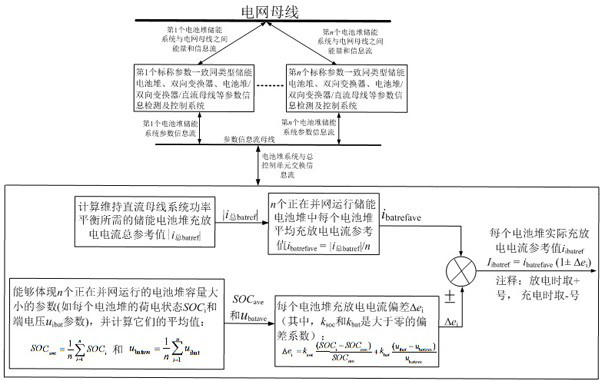
[0030] Please refer to the attached figure 1 , the technical problem to be solved in this embodiment is that there is an error in the existing method of distributing the charge and discharge current only by the SOC of the battery stack, so a method for controlling the charge and discharge current of a parallel battery energy storage system is provided. The present invention mainly For the same type of battery stacks with the same nominal parameters, the charging and discharging current control methods of the parallel battery energy storage system include:

[0031] The grid bus, the parameter information flow bus, multiple battery stack energy storage systems and the general control unit, the grid bus is electrically connected to multiple battery stack energy storage systems at the same time, and the multiple battery stack energy storage systems are simultaneously electrically connected to the parameter information flow bus, The parameter information flow bus is electrically conn


PUM


Abstract

The invention discloses a charging and discharging current control method for a parallel battery energy storage system. The method comprises the following steps: carrying out serial number calibration on a plurality of battery stack energy storage systems which are operated in parallel in the energy storage system, and respectively receiving system parameter information flow of each battery stack energy storage system; calculating a total reference value of charging and discharging currents of the cell stack energy storage system required for maintaining power balance of the power grid bus system, and calculating an average reference value of the charging and discharging currents; calculating the battery stack charge state and terminal voltage of each battery stack energy storage system, calculating the average value of the battery stack charge state of the battery stack energy storage system, calculating the average value of the battery stack terminal voltage of the battery stack energy storage system, and calculating the charge and discharge current deviation of each battery stack according to the average value and the average value; calculating an actual charging and discharging current reference value of each cell stack energy storage system; and carrying out charge and discharge current control on each cell stack energy storage system through a master control unit. The method has the advantages of prolonging the service life of the cell stack and ensuring good performance of the cell stack.

Description


Claims


Application Information

Patent Timeline
Owner IANGSU COLLEGE OF ENG & TECH
Why Eureka
Try Eureka