Rigidity-adjustable particle damper for high-rise civil structure

A technology for structure and shock absorber, applied in the direction of earthquake resistance, building components, building types, etc., can solve the problems of narrow vibration reduction frequency band, single vibration control, sensitive to changes in the working environment, etc., and achieve the effect of preventing deformation.

Active Publication Date: 2021-08-10
XIJING UNIV
View PDF9 Cites 0 Cited by
  • Summary
  • Abstract
  • Description
  • Claims
  • Application Information

AI Technical Summary

Benefits of technology

This patented technology improves upon existing methods for controllably reducing movement caused during an explosion or other type of event (such as blasts). It achieves this through use of springs made up mostly of multiple rodlets inside each section within the device itself instead of just one single rodlet per section. By adding these features, the overall size of the device becomes smaller while still providing effective shock reduction capabilities. Additionally, there's no longer any chance of losing control over how long they extend outwardly due to gravity waves hitting their surface before being fully deployed again.

Problems solved by technology

The technical problem addressed by this patented technology relates to improving or optimizing the design of an active damping system that can efficiently suppress both passively generated vibrations caused by building movements and induced ones from external sources like lightning strikes.

Method used


Image

  • Rigidity-adjustable particle damper for high-rise civil structure
  • Rigidity-adjustable particle damper for high-rise civil structure
  • Rigidity-adjustable particle damper for high-rise civil structure

Examples


Embodiment

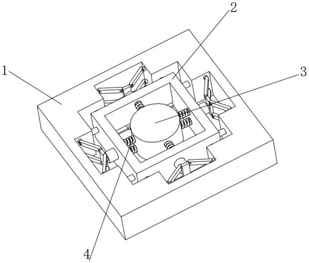
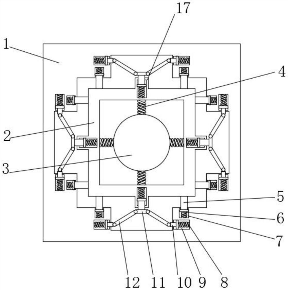
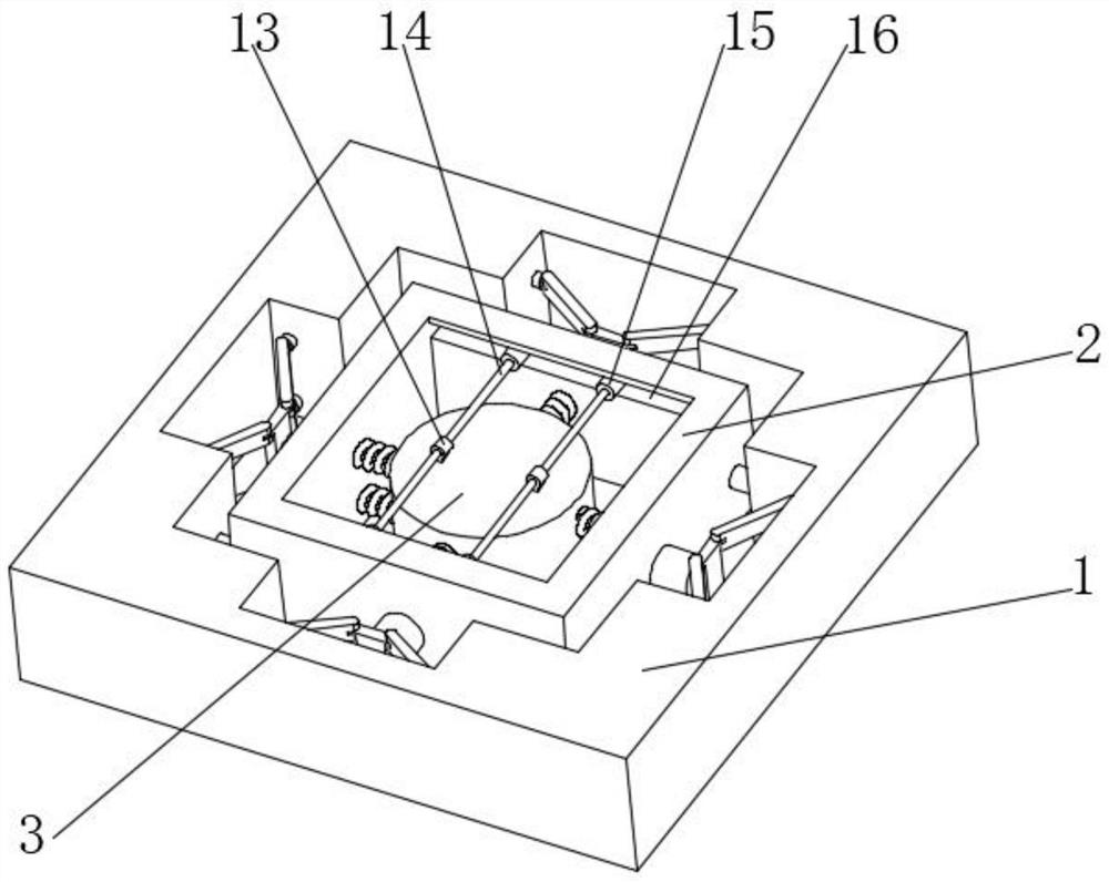
[0023] see Figure 1-6 , the present invention provides the following technical solutions: a particle shock absorber with adjustable stiffness for high-rise civil structures, including a main body 1, a frame body 2 is installed inside the main body 1, and a second groove 7 is provided at both ends of the main body 1, The inside of the second groove 7 is equipped with a second spring 6, and one end of the second spring 6 is equipped with a second guide rod 5, and the end of the second guide rod 5 away from the second spring 6 is equipped with a frame body 2, and the second groove 7 is provided with a first groove 9 below, and a first spring 8 is installed inside the first groove 9, and a first guide rod 10 is installed on one end of the first spring 8, and the first guide rod 10 is far away from the side of the first spring 8. One end is rotatably connected with a connecting rod 12, a box body 3 is installed inside the frame body 2, a spring device 4 is installed on the inner wall


PUM


Abstract

The invention belongs to the technical field of shock absorbers, and particularly relates to a rigidity-adjustable particle shock absorber for a high-rise civil structure. The rigidity-adjustable particle shock absorber comprises a main body; a frame body is mounted in the main body; second grooves are formed in two ends in the main body; second springs are mounted in the second grooves; second guide rods are mounted at one ends of the second springs; the frame body is installed at the ends, away from the second springs, of second guide rods; a first groove is formed below each second groove; a first spring is installed in each first groove; a first guide rod is installed at one end of each first spring, and a connecting rod is rotationally connected to the end, away from the first spring, of each first guide rod; a box body is mounted in the frame body; a spring device is installed on the inner wall of the frame body, and the frame body is connected with the box body through the spring device; sliding rings are installed at the bottom end of the box body; and sliding rods are slidably connected to the inner side walls of the sliding rings. The problems that a damper is single in control vibration, and multi-vibration control cannot be effectively conducted are solved.

Description


Claims


Application Information

Patent Timeline
Owner XIJING UNIV
Why Eureka
Try Eureka