Antenna insertion electrode structure and image display device

A technology of inserting electrodes and antenna patterns, which is applied to antenna supports/installation devices, radiating element structures, circuits, etc., can solve problems such as difficulty in easily forming radiating electrodes and image quality degradation of image display devices.

Pending Publication Date: 2021-08-17
DONGWOO FINE CHEM CO LTD
View PDF1 Cites 3 Cited by
  • Summary
  • Abstract
  • Description
  • Claims
  • Application Information

AI Technical Summary

Problems solved by technology

For example, if a touch sensing electrode is formed together with a radiation electrode of an antenna, it may be difficult to easily form a radiation electrode of a desired shape for realizing a predetermined radiation characteristic.

Method used


Image

  • Antenna insertion electrode structure and image display device
  • Antenna insertion electrode structure and image display device
  • Antenna insertion electrode structure and image display device

Examples


Embodiment Construction

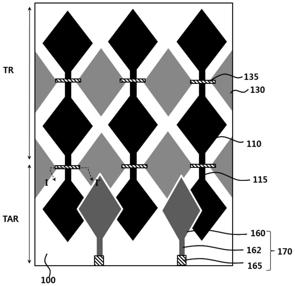
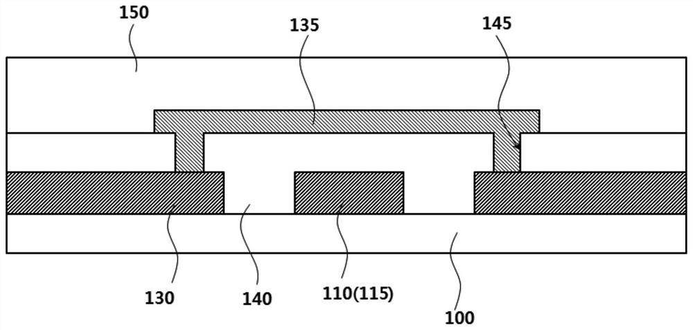
[0038] According to an exemplary embodiment of the present invention, there is provided an antenna insertion type electrode structure including an antenna pattern and a sensing electrode in the same plane. In addition, an image display device including the antenna-inserted electrode structure is provided.

[0039] Hereinafter, the present invention will be described in detail with reference to the accompanying drawings. However, those skilled in the art will understand that such embodiments described with reference to the accompanying drawings are provided for further understanding of the spirit of the present invention and do not limit the claimed subject matter disclosed in the detailed description and the appended claims.

[0040] The terms "first direction", "second direction", "third direction", "fourth direction", "column direction" and "row direction" used herein are not intended to denote absolute specific directions, but are used for Different directions are relatively


PUM


Abstract

The invention relates to an antenna insertion electrode structure and image display device. The antenna insertion electrode structure comprises: a substrate layer including a touch sensing region and a touch sensing-antenna region; sensing electrodes arranged on the touch sensing region and the touch sensing-antenna region of the substrate layer; and an antenna pattern arranged on the touch sensing-antenna region of the substrate layer and including a radiation pattern. The sensing electrodes and the radiation pattern include a hybrid mesh structure, and the hybrid mesh structure includes a first mesh structure and a second mesh structure having different shapes and arrangements and being integrally coupled to each other.

Description


Claims


Application Information

Patent Timeline
Owner DONGWOO FINE CHEM CO LTD
Why Eureka
Try Eureka