Coaxial electromagnetic valve for deep sea and using method

A solenoid valve, coaxial technology, applied in the field of solenoid valve, can solve the problem that the solenoid valve cannot be used in the harsh environment of the deep sea, and achieve the effect of avoiding residual magnetism, smooth movement, and stable and reliable solenoid valve switching.

Active Publication Date: 2021-10-08
余姚市三力信电磁阀有限公司
View PDF11 Cites 0 Cited by
  • Summary
  • Abstract
  • Description
  • Claims
  • Application Information

AI Technical Summary

Problems solved by technology

[0005] The problem to be solved by the present invention is to provide a coaxial solenoid valve for deep sea and its use m

Method used


Image

  • Coaxial electromagnetic valve for deep sea and using method
  • Coaxial electromagnetic valve for deep sea and using method
  • Coaxial electromagnetic valve for deep sea and using method

Examples


Example Embodiment

[0037] DETAILED DESCRIPTION OF THE PREFERRED EMBODIMENTS The following examples are intended to illustrate the invention, but are not intended to limit the scope of the invention.

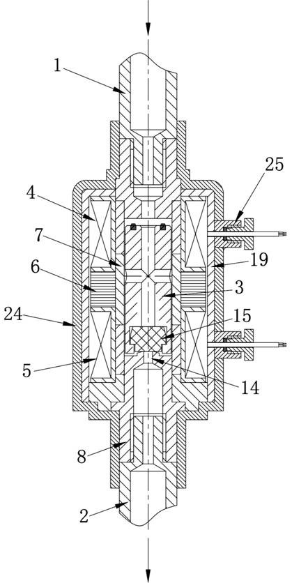
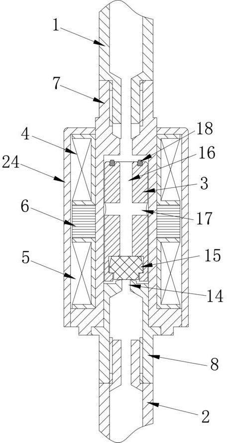
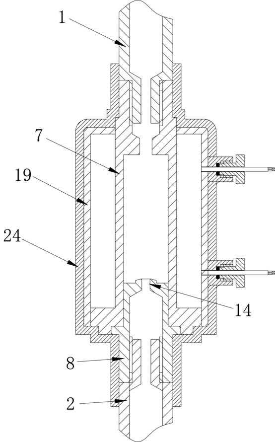
[0038] See Figures 1 to 10The present invention provides a deep coaxial solenoid valve comprises an inlet pipe 1, outlet pipe 2, the magnetic barrier tube assembly for the valve body 7 and the activities of the inlet pipe 2 and an outlet communicating or blocking a pipe 3, the inlet pipe 1 2 and outlet pipe coaxially disposed, the movable valve element 3 is made of iron, the outer spool axially 3 activity sequentially attached to the first coil 4 and second coil 5 is mounted between the first coil 4 and second coil 5 there magnet 6, different from the first coil 4 and second coil 5 of the pulse signal access. Wherein the active spool 3 slidably mounted in the tube separated from the magnetic assembly 7, a first coil 4, the magnet 6 and the second coil 5 are sequentially mounted on the outside of the magne


PUM


Abstract

The invention provides a coaxial electromagnetic valve for deep sea and a using method. The electromagnetic valve comprises an inlet pipe, an outlet pipe and a movable valve element used for communicating or separating the inlet pipe and the outlet pipe, the inlet pipe and the outlet pipe are coaxially arranged, and a first coil and a second coil are sequentially installed on the outer side of the movable valve element in the axial direction; magnetic steel is mounted between the first coil and the second coil, and pulse signals accessed by the first coil and the second coil are different in direction; the using method comprises the following steps that the pulse signals in different directions are connected to the first coil and the second coil at the same time and matched with the magnetic steel mounted between the first coil and the second coil, so that the movable valve element is controlled to slide, and the inlet pipe and the outlet pipe are communicated or separated; and according to the coaxial electromagnetic valve for the deep sea and the using method, the defect that an existing electromagnetic valve cannot be suitable for the deep sea environment is overcome.

Description


Claims


Application Information

Patent Timeline
Owner 余姚市三力信电磁阀有限公司
Why Eureka
Try Eureka