Underground infrastructure leakage water state identification method and system

A technology of infrastructure and identification method, which is applied in the field of identification method and system of seepage water behavior of underground infrastructure, can solve the problem of low prediction accuracy and achieve high identification accuracy

Active Publication Date: 2021-10-19
BEIHANG UNIV
View PDF7 Cites 1 Cited by
  • Summary
  • Abstract
  • Description
  • Claims
  • Application Information

AI Technical Summary

Benefits of technology

This patented technology allows us to accurately detect leaks from underground structures such as pipelines or tunnels without being affected by any factors like temperature changes over different periods during their operation. It also includes an algorithm that combines multiple images taken through these structures together into one more accurate picture of how they are going damaging due to damage caused by liquid spills on surfaces. Overall, this technique helps improve safety measures against groundwater contamination while minimizing economic losses associated therewith.

Problems solved by technology

This patented technical solution describes how we want to improve understanding about the behaviors of underwater structures caused from environmental changes like rain fall over time. Existing methods rely heavily on manual labor and cannot provide accurate predictions when faced with complicated situations involving multiple layers that require detailed analysis. Computerized tomography (CT) imaging provides an effective way to detect leaks during excavations without requiring human intervention. Computational Fluid Dynamics (CFD), which involves analyzing fluid flow through pipelines, allows us to predict future pipeline movements accurately despite being exposed constantly at varying levels of pressure.

Method used


Image

  • Underground infrastructure leakage water state identification method and system
  • Underground infrastructure leakage water state identification method and system
  • Underground infrastructure leakage water state identification method and system

Examples


Embodiment Construction

[0057] The following will clearly and completely describe the technical solutions in the embodiments of the present invention with reference to the accompanying drawings in the embodiments of the present invention. Obviously, the described embodiments are only some, not all, embodiments of the present invention. Based on the embodiments of the present invention, all other embodiments obtained by persons of ordinary skill in the art without making creative efforts belong to the protection scope of the present invention.

[0058] The purpose of the present invention is to provide a method and system for identifying the seepage water behavior of underground infrastructure, which can improve the identification accuracy in complex and diverse underground environments.

[0059] In order to make the above objects, features and advantages of the present invention more comprehensible, the present invention will be further described in detail below in conjunction with the accompanying drawi


PUM


Abstract

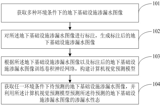
The invention relates to an underground infrastructure leakage water state identification method and system. The method comprises the following steps: acquiring underground infrastructure water leakage images under various environmental conditions; marking the underground infrastructure water leakage image, and generating a marked underground infrastructure water leakage image; training a convolutional neural network according to the underground infrastructure water leakage image and the marked underground infrastructure water leakage image, and constructing a computer vision prediction model; and obtaining a to-be-predicted underground infrastructure water leakage image under any environmental condition, and predicting the water leakage state of the to-be-predicted underground infrastructure water leakage image by using the computer vision prediction model. According to the method, the identification precision in complex and diverse underground environments can be improved.

Description


Claims


Application Information

Patent Timeline
Owner BEIHANG UNIV
Why Eureka
Try Eureka