Concrete density detector for municipal engineering detection

A technology for engineering inspection and concrete, applied in the field of concrete density detector, can solve the problems of small test range, deviation in accuracy, inconvenient measurement, etc., and achieve the effects of convenient use, expansion of test range and high precision

Inactive Publication Date: 2021-11-16
聂大伟
View PDF0 Cites 0 Cited by
  • Summary
  • Abstract
  • Description
  • Claims
  • Application Information

AI Technical Summary

Problems solved by technology

[0003] Since it is difficult for the ultrasonic detector to accurately measure the strength of the concrete, the core drilling method is not easy to sample, so the rebound method is often used during construction, which can more conveniently and accurately detect whether the concrete density is qualified, but the use of the rebound method A concrete rebound te

Method used


Image

  • Concrete density detector for municipal engineering detection
  • Concrete density detector for municipal engineering detection
  • Concrete density detector for municipal engineering detection

Examples


Embodiment Construction

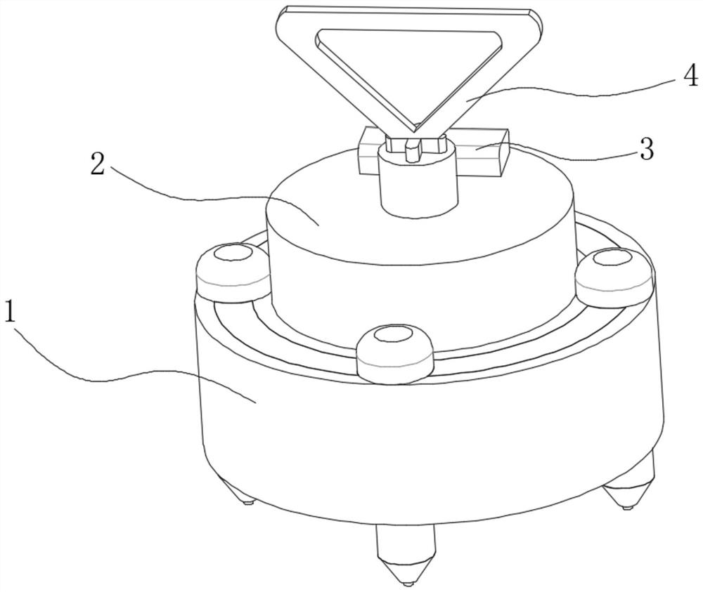
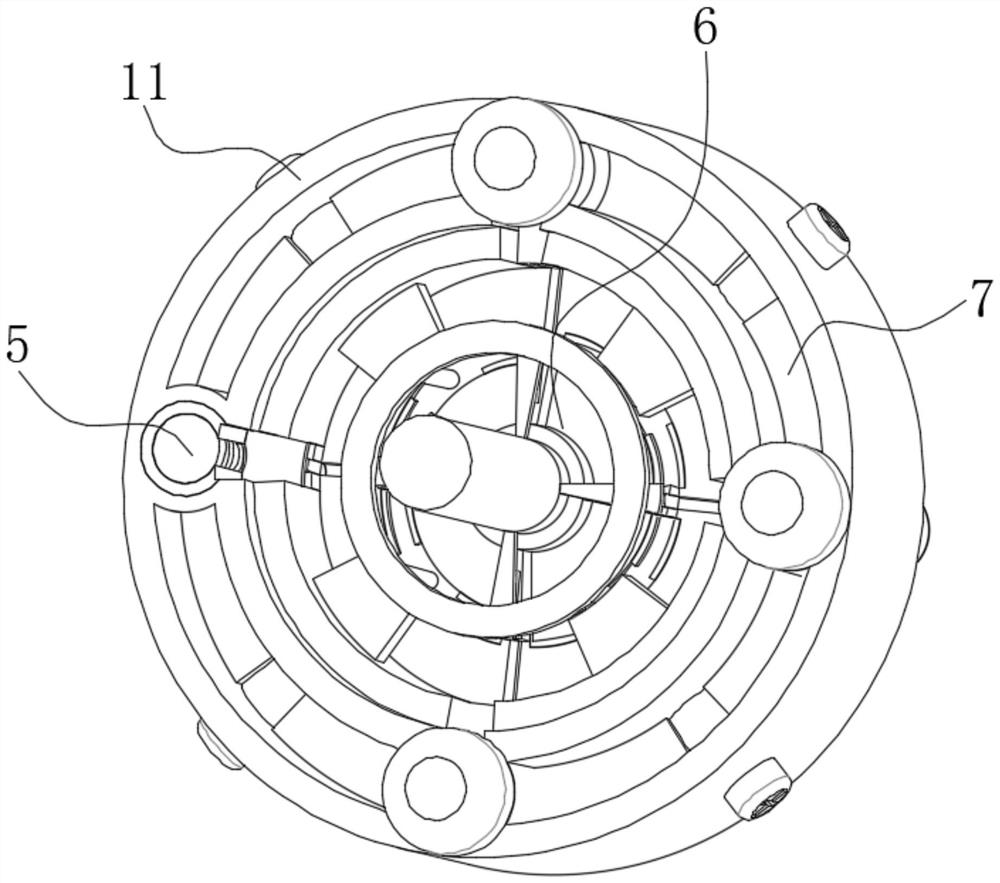
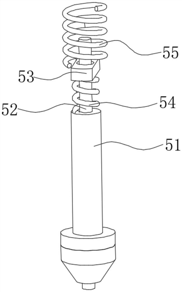
[0024] use Figure 1-Figure 6 A concrete density detector for municipal engineering detection according to an embodiment of the present invention is described as follows.

[0025] Such as Figure 1-Figure 6 As shown, a concrete density detector for municipal engineering detection according to the present invention includes a rebound hammer 1, and the inner cavity of the rebound hammer 1 is fixedly connected with an external column 2, and the outer surface of the external column 2 is The lower part is fixedly connected with the inner wall of the hammer 1, and the upper surface of the external column 2 is fixedly connected with a display meter 3, and the inner cavity of the display meter 3 is fixedly connected with the inner cavity of the rebound hammer 1 by electric wires. The axis of the column 2 is fixedly connected with a handle 4 through an opening, and the bottom end of the handle 4 is fixedly connected with the inner chamber of the rebound hammer 1 through the connecting co


PUM


Abstract

The invention belongs to the field of engineering detection, and particularly relates to a concrete density detector for municipal engineering detection. The concrete density detector comprises a rebound apparatus, the lower portion of the outer surface of an external column is fixedly connected with the inner wall of the rebound apparatus, and a display meter is fixedly connected to the upper surface of the external column; an inner cavity of the display meter is fixedly connected with an inner cavity of the rebound apparatus through an electric wire, a lifting handle is fixedly connected to the axis of the external connection column through an open hole, and the bottom end of the lifting handle is fixedly connected with the inner cavity of the rebound apparatus through a connection column. When the device is used, a user can easily apply force to the device, different from a common rebound apparatus, the rebound apparatus part of the device is provided with four groups of test points, four groups of data can be obtained after the device is used for testing once, the average density of concrete at the position can be obtained through simple calculation of a display meter, more accurate and reliable data can be obtained, the test range is expanded, and the use is more convenient.

Description


Claims


Application Information

Patent Timeline
Owner 聂大伟
Why Eureka
Try Eureka