Optical detector with precise positioning function

An optical detector and precise positioning technology, applied in the field of optical detection, can solve the problems of affecting the detection accuracy, easy adhesion of dust on the surface of the lens, inconvenient clamping of the magnifying lens, etc., to improve accuracy, prevent offset, and facilitate use quick effect

Pending Publication Date: 2021-11-26
深圳市象形科技有限公司
View PDF0 Cites 0 Cited by
  • Summary
  • Abstract
  • Description
  • Claims
  • Application Information

AI Technical Summary

Benefits of technology

This patented technology allows an optoelectrode (EO) camera or other sensor used to detect contamants such as dirt on surfaces without interferring their performance. It uses specialized equipment called a cleaner to remove any debris left over during manufacturing processes. By aligning the EO's objective lens with specific dimensions, there are also multiple ways to adjust its focus distance based upon these measurements. Additionally, the system includes various components like sensors, transmitting rings, supporting crossbars, guiding tubular sheaths, mountings, and connect cassettes. These components help maintain accurate alignment between them while they work together smoothly. Overall, this technology improves the efficiency and reliability of inspections performed through laser scanning systems.

Problems solved by technology

This patented technical problem addressed by this patents relates to improving the precision and consistency during manufacturing processes when holding or fixing an objective lens that has uneven surfaces on its edges due to factors like dust accumulation from external sources such as airflow over it's surface.

Method used


Image

  • Optical detector with precise positioning function
  • Optical detector with precise positioning function
  • Optical detector with precise positioning function

Examples


Embodiment Construction

[0030] The present invention will be further described below in conjunction with the accompanying drawings and embodiments.

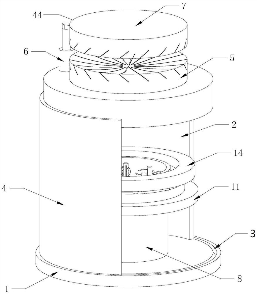
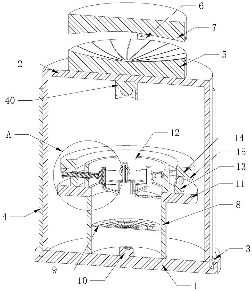
[0031] see Figure 1-6 , the present invention provides a technical solution: an optical detector with precise positioning function, including a base 1, a housing 2 is fixedly installed on the top of the base 1, and a moving chute is provided on the top of the base 1 and outside the housing 2 3. The interior of the moving chute 3 is installed with a shading plate 4 through bearing rotation, a cleaning device 44 is installed on the top of the housing 2, and a shading tube 8 is fixedly installed on the top of the base 1 and inside the housing 2, and the inner wall of the shading tube 8 And be positioned at the position close to the middle and be fixedly installed with the display negative film 9, the top of the base 1 and be positioned at the position in the middle are fixedly installed with the collection camera 10, the inner wall of the top of the housing


PUM


Abstract

The invention provides an optical detector with a precise positioning function, and relates to the field of optical detection. The optical detector with the precise positioning function comprises a base, a shell is fixedly installed at the top of the base, a movable sliding groove is formed in the position, located on the outer side of the shell, of the top of the base, and a shading plate is rotationally installed in the movable sliding groove through a bearing. According to the optical detector with the precise positioning function, magnifying lenses with different sizes can be clamped and fixed, so that a clamp does not need to be replaced when the magnifying lenses with different sizes are clamped, and the optical detector is convenient and rapid to use, the center positions of the magnifying lenses can be kept at the same position when the magnifying lenses with different diameters and thicknesses are clamped, so that the clamping and positioning accuracy is improved, and finally, the imaging is performed through irradiation, and the imaged image is shot and stored through the acquisition camera, whether the magnifying lens is qualified or not can be determined through distribution of imaging light spots.

Description


Claims


Application Information

Patent Timeline
Owner 深圳市象形科技有限公司
Why Eureka
Try Eureka