Inverter device
A technology of inverter and control device, applied in the direction of electronic commutator, electrical components, control system, etc., can solve the problem of vehicles not starting, and achieve the effect of improving torque
- Summary
- Abstract
- Description
- Claims
- Application Information
AI Technical Summary
Benefits of technology
Problems solved by technology
Method used
Image

Examples
Embodiment approach 1
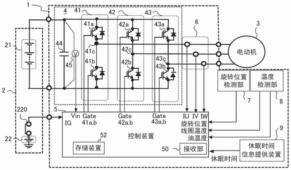
[0028] figure 1 It is a block diagram of the motor drive device of Embodiment 1. In addition, in the drawings, the same reference numerals represent the same or corresponding parts.
[0029] Such as figure 1 As shown, the inverter device 1 is composed of an inverter 4 that converts a direct current from a power source 2 into an alternating current and inputs it to a motor 3 , and a control device 5 that controls the inverter 4 . exist figure 1 Among them, the power supply 2 includes a high-voltage power supply system 21 and a low-voltage power supply system 22 . The high-voltage power supply system 21 supplies power to the motor 3 through the inverter 4 . The low-voltage power supply system 22 is configured to supply power to the control device 5 of the inverter device 1 . A contactor 220 is provided between the low-voltage power supply system 22 and the control device 5 to perform electrical on / off.
[0030] The inverter 4 includes a first voltage conversion circuit 41 f
Embodiment approach 2
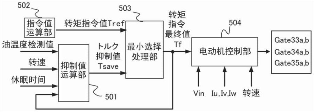
[0059] In this second embodiment, a part of the suppression value calculation unit 501 of the first embodiment is changed, as follows Figure 10 As shown, the detection value Tcoil of the coil temperature of the electric motor 3 is input to the startup processing part 501g, and it is comprised so that calculation may be performed. which is, Figure 10 is a block diagram showing the configuration of the suppression value calculation unit 501 . Here, the detection value of the coil temperature is input to the startup processing unit 501g, which is the same as Figure 4 different.
[0060] Next, refer to Figure 11 The flowchart of FIG. 2 illustrates the processing in the startup processing unit 501g of the second embodiment.
[0061] In step S21, it is determined whether or not the state of the inverter device 1 is at startup. When the state of the inverter device 1 is in operation, in step S22, the previous value Td of the torque command value Tref is used as the activation v
PUM
 Abstract
Description
Claims
Application Information
 - R&D Engineer
- R&D Manager
- IP Professional
- Industry Leading Data Capabilities
- Powerful AI technology
- Patent DNA Extraction
Browse by: Latest US Patents, China's latest patents, Technical Efficacy Thesaurus, Application Domain, Technology Topic.
© 2024 PatSnap. All rights reserved.Legal|Privacy policy|Modern Slavery Act Transparency Statement|Sitemap