Sealing structure of air spring
A sealing structure and air spring technology, which is applied in the direction of springs, spring/shock absorbers, gas shock absorbers, etc., can solve the problems of O-ring seal damage, air spring failure, etc., to improve sealing performance, increase deformation performance, The effect of avoiding damage
- Summary
- Abstract
- Description
- Claims
- Application Information
AI Technical Summary
Problems solved by technology
Method used
Image

Examples
Example Embodiment
[0030] Example one
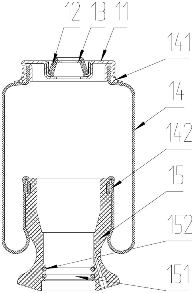
[0031] See Figure 1-3 The sealing structure of an air spring includes an upper end cover 11, a sacral article 14, and a piston seat 15, which is made of a mixed rubber material; one side of the bladder 14 is connected to the upper end cover 11, the sacral article 14 The other side is connected to the piston seat 15, which is connected to the upper end cover 11, the vesicle skin 14, and the piston seat 15, and the connection ensures sufficient seal, preferably, the feeding 14 and the upper end cover 11 pass the clamp 141 is fixed, and the bladder 14 is fixed between the piston seat 15 by the lower buckle 142.
[0032] The sealing of the piston seat 15 is in a radial seal, and the sealing groove 151 is provided in the piston seat 15, and the sealing groove 151 is embedded in the sealing ring 152, preferably, the sealing ring 152 adopts an O shape. The seal ring 152 is in use, since the inner diameter of the sealing ring 152 is smaller than the inner diameter of the
Example Embodiment
[0035] Example 2
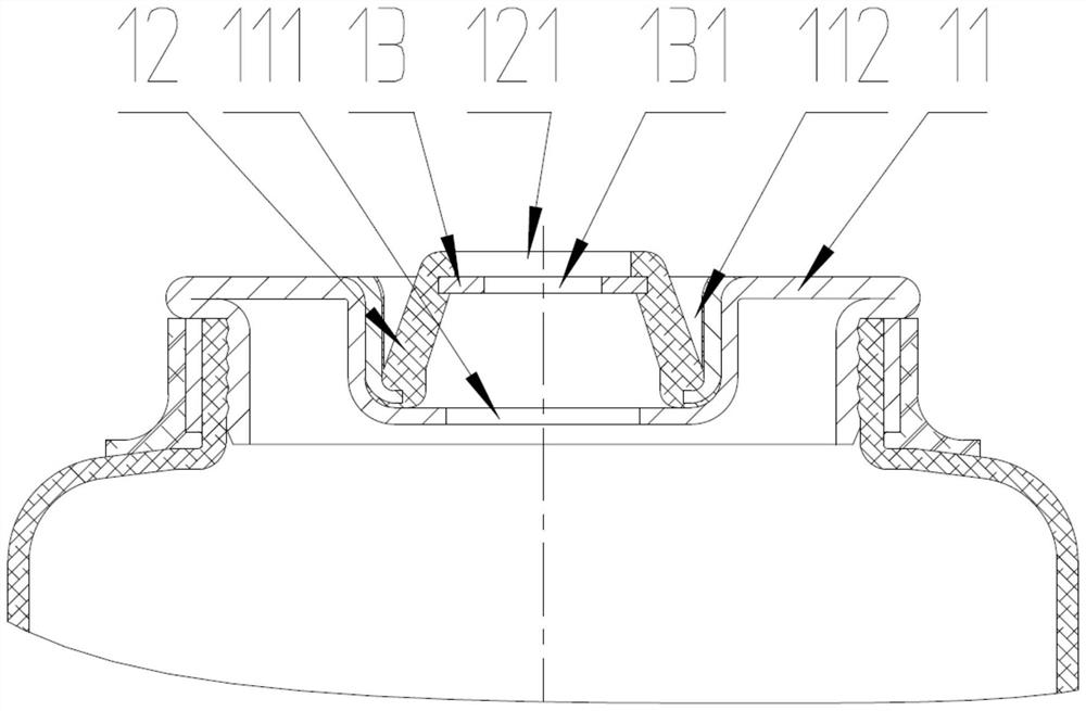
[0036] Embodiment 2 is a further explanation of the embodiments, the same components are not described here, see Figure 1-3 The upper end cover 11 is provided with a mounting groove 112, preferably, and the upper end cover 11 and the sealing plate 13 are made of a cold rolled steel sheet material, and the stamped molding is directly formed, that is, the mounting groove 112 is also stamped. Pressure molding is lighter than the original cast steel piece; the first mounting hole 111 is opened within the mounting groove 112, and the sealing sleeve 12 is disposed within the mounting groove 112.
[0037] When used, the air spring will make a stretch, which will cause a certain deformation to generate a certain deformation, and the sealing sleeve 12 is disposed in the mounting groove 112, which can effectively limit the parameter direction of the sealed cover 12 to avoid the sealing sleeve 12 to deviate from the shaft, causing air. The instability of the spring.
Example Embodiment
[0038] Example three
[0039] The third embodiment is a further explanation of the second embodiment, and the same components will not be described here. Figure 1-3 The sealing sleeve 12 is rounded, and the lower end of the sealing sleeve 12 is tested in the mounting groove 112, and the connection point is sealed; preferably, the mounting groove 112, the sealing sleeve 12, and the sealing plate 13 are formed in a vulcanization. To the full seal; the sealing sleeve 12 is placed in a round stage, and the deformation performance is increased on one hand, and since the side of the sealing sleeve 12 is inclined, it can be effective in the sealing sleeve 12 in the sealing sleeve 12. Restrict its deformation direction, avoiding the sealing sleeve 12 off the shaft core, causing the unstable air spring.
[0040] It will be noted here that the first mounting hole 111, the axis of the second mounting holes 121 and the third mounting hole 131 are both the same straight.
PUM
 Abstract
Description
Claims
Application Information
 - R&D Engineer
- R&D Manager
- IP Professional
- Industry Leading Data Capabilities
- Powerful AI technology
- Patent DNA Extraction
Browse by: Latest US Patents, China's latest patents, Technical Efficacy Thesaurus, Application Domain, Technology Topic.
© 2024 PatSnap. All rights reserved.Legal|Privacy policy|Modern Slavery Act Transparency Statement|Sitemap