Light-emitting device and display device

A technology for light-emitting devices and components, applied in the field of light-emitting semiconductors and backlight displays, can solve the problems of reduced light emission, dark areas of chip light emission, etc., and achieve the effects of small light mixing distance, thin overall brightness, and improved light intensity.

Active Publication Date: 2022-01-04
HGC (WUHAN) TECH CO LTD
View PDF7 Cites 0 Cited by
  • Summary
  • Abstract
  • Description
  • Claims
  • Application Information

AI Technical Summary

Benefits of technology

This patented technology allows for better control over how much light comes into view on an LED screen or LCD panel. It uses special parts called lenses made up of different materials like glasses or plastic foils instead of traditional screens. By focusing this ray onto specific areas within these layers, it becomes more visible than other methods due to its longer wave length converted color range. Additionally, when mixed together, less energy goes towards achieving higher intensity compared to previous designs without any improvements. Overall, this design improves both performance and efficiency of LED displays while reducing their thickness and weight.

Problems solved by technology

This patented problem addressed in the technical problem described by the patents relates to improving the efficiency or brightness of thin film transistor liquid crystal displays used for electronic devices such as smartphones due to their compact design with fewer components needed compared to regular LCD panels.

Method used


Image

  • Light-emitting device and display device
  • Light-emitting device and display device
  • Light-emitting device and display device

Examples


Embodiment Construction

[0041] In order to facilitate the understanding of the present invention, the present invention will be described more fully below with reference to the associated drawings. Preferred embodiments of the invention are shown in the accompanying drawings. However, the present invention can be embodied in many different forms and is not limited to the embodiments described herein. On the contrary, these embodiments are provided to make the understanding of the disclosure of the present invention more thorough and comprehensive.

[0042] It should be noted that when an element is referred to as being “fixed” to another element, it can be directly on the other element or there can also be an intervening element. When an element is referred to as being "connected to" another element, it can be directly connected to the other element or intervening elements may also be present.

[0043] Unless otherwise defined, all technical and scientific terms used herein have the same meaning as co


PUM


Abstract

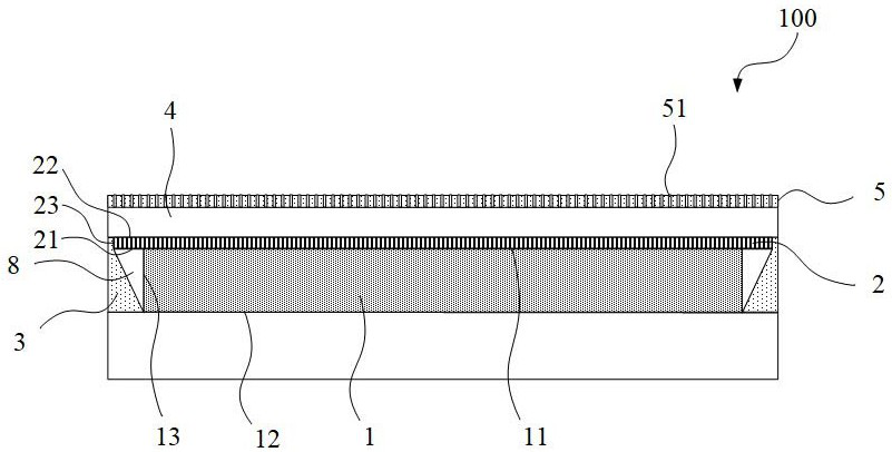
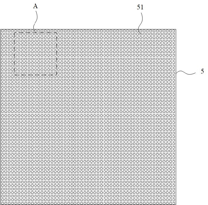
The invention provides a light-emitting device and a display device. The light-emitting device extracts light emitted from a side surface (a second light-emitting surface) of a semiconductor light source through a light extraction member, collects the light from the side surface to a top part, emits the light together with a first light-emitting surface to a wavelength conversion member, and emits white light from the top part (a second contact surface) of the wavelength conversion member. After passing through the light-transmitting layer, the white light is emitted through the thickness direction of the light-transmitting layer and the top provided with the light suppression layer, and the top white light is partially suppressed by the light suppression layer. According to the light-emitting device, the overall light emitting intensity can be improved, top light emitting can be partially restrained, the situation that in the prior art, the top is directly and completely restrained, a dark area appears on the top, and an overall brightness loss is too large is avoided, in addition, when the light-emitting device is used in the display device, the light mixing distance can be very small, and the display device is thinner and high in overall brightness.

Description


Claims


Application Information

Patent Timeline
Owner HGC (WUHAN) TECH CO LTD
Why Eureka
Try Eureka