High-efficiency and high-precision quartz glass tube forming equipment
A quartz glass tube and forming equipment technology, applied in glass manufacturing equipment, glass forming, glass pressing, etc., can solve problems such as pressing tilt, different thicknesses on both sides of the glass tube, and inability to perform precise positioning, so as to promote rapid flow , The effect of improving the overall forming accuracy
- Summary
- Abstract
- Description
- Claims
- Application Information
AI Technical Summary
Benefits of technology
Problems solved by technology
Method used
Image

Examples
Embodiment 1
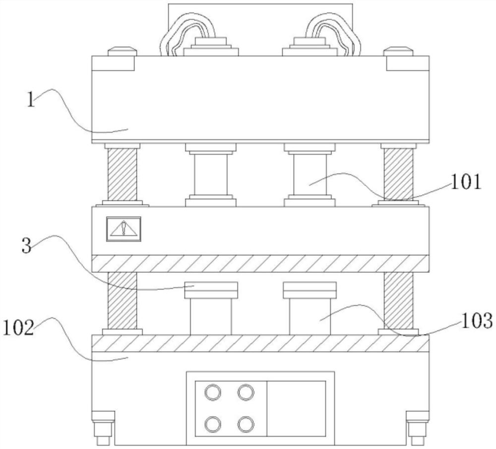
[0036] Embodiment 1: A high-efficiency and high-precision quartz glass tube forming equipment, including a press 1, a pressure column 101 slides on the upper end of the press 101, a base 102 is installed on the lower end of the press 1, and a mold 103 is installed on the upper end of the base 102 , the inner side of the mold 103 is provided with a folding mechanism that can improve precision and a transmission mechanism that utilizes thermal expansion and cold contraction to recover glass liquid;
[0037] Among them: the upper end of the press 101 is equipped with a hydraulic pump, the hydraulic pump is set up with the pressure column 101, the pressure column 101 is vertically corresponding to the mold 103, the lower end of the pressure column 101 is provided with a groove, and the pressure column 101 is vertically embedded in the mold The inside of 103 is embedded in the inside of the pressure column 101 by using a folding mechanism, which can facilitate the precise docking of th
Embodiment 2
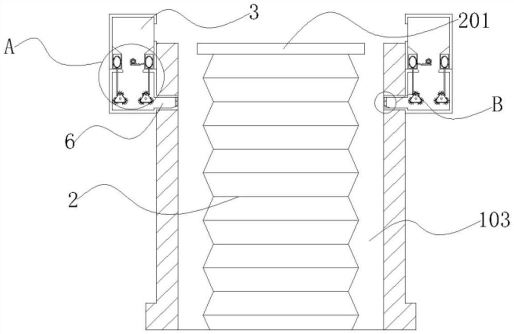
[0038] Embodiment 2: with reference to instruction manual image 3 It can be seen that the difference between embodiment 2 and embodiment 1 is that the folding mechanism includes a folding tube 2 and a clamping block 201, the folding tube 2 is folded and stretched inside the mold 103, and the clamping block 201 slides on the upper end of the folding tube 2;
[0039] Wherein: the folding tube 2, the folding tube 2 is arranged in a wave shape, the folding tube 2 is arranged at the center position inside the mold 103, and the folding tube 2 and the pressure column 101 are vertically sliding and nested;
[0040] The clamping block 201, the clamping block 201 and the folding tube 2 are arranged in a "T" shape as a whole, when the pressure column 101 is embedded in the mold 103, the clamping block 201 and the pressure column 101 are fitted;
[0041] Wherein: when the pressure column 101 is embedded in the mold 103, the clamp block 201 is fitted with the pressure column 101, and the cla
Embodiment 3
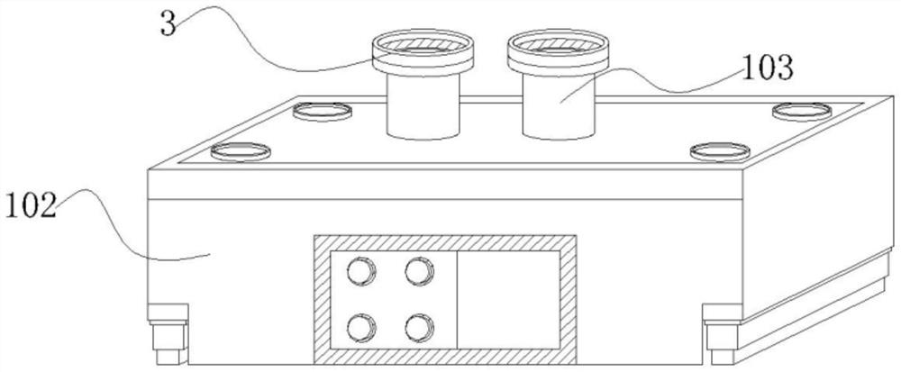
[0042] Embodiment 3: with reference to instruction manual image 3 , 5and 6, it can be seen that the difference between embodiment 3 and embodiments 1 and 2 is that the transmission mechanism includes a sleeve 3, a gear 301, a connecting rod 302, a tooth piece 303, a scraper 304 and a rotating shaft 305, and the sleeve 3 is sleeved on On the upper end of the mold 103, the gear 301 rotates on the upper end inside the sleeve 3, the connecting rod 302 rotates around the outside of the gear 301, the tooth piece 303 is arranged on one side of the connecting rod 302, and the scraper 304 is embedded on the other side of the connecting rod 302. On one side, the rotating shaft 305 rotates on the side of the connecting rod 302;
[0043] Wherein: the sleeve 3, the side of the upper end of the sleeve 3 is provided with an opening, the opening fits with the upper end of the mold 103, and the inside of the sleeve 3 is hollow;
[0044] The gear 301, the gear 301 is vertically arranged inside
PUM
 Abstract
Description
Claims
Application Information
 - R&D Engineer
- R&D Manager
- IP Professional
- Industry Leading Data Capabilities
- Powerful AI technology
- Patent DNA Extraction
Browse by: Latest US Patents, China's latest patents, Technical Efficacy Thesaurus, Application Domain, Technology Topic.
© 2024 PatSnap. All rights reserved.Legal|Privacy policy|Modern Slavery Act Transparency Statement|Sitemap