Mechanical drive control type flow regulating valve
A flow regulating valve, mechanically driven technology, applied in the direction of mechanical equipment, valve details, safety valves, etc., can solve the problems of large space size for installing solenoid valves, complex electromagnetic design, high manufacturing and maintenance costs, and achieve independent size and weight Restricted, compact structure, wide range of effects
- Summary
- Abstract
- Description
- Claims
- Application Information
AI Technical Summary
Problems solved by technology
Method used
Image

Examples
Embodiment 1
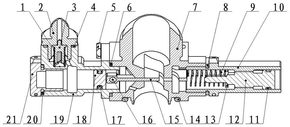
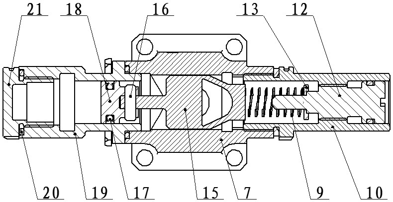
[0027] A mechanically actuated control type flow regulating valve, such as figure 1 , figure 2 As shown, it includes a pressure control cavity, a valve seat 7, an adjustment system, a piston 18, and a restrictor plate 15. The adjustment system includes an adjustment seat 10, a screw plug 12 and a rectangular spring 9 arranged inside the adjustment seat 10; The left and right sides of the valve seat 7 are respectively connected with a pressure control chamber and an adjustment seat 10. The piston 18 is slidably arranged in the pressure control chamber, and a flow-limiting passage is arranged in the valve seat 7. The valve seat 7 The two sides of the corresponding flow limiting plate 15 are provided with slideways. The flow limiting plate 15 slides through the flow limiting channel, and the two ends are respectively connected to the slideway. The flow limiting plate 15 is used to control the flow of the flow limiting channel. Flow cross-sectional area, a throttling port is formed
Embodiment 2
[0033] This embodiment is optimized on the basis of Embodiment 1. The pressure control chamber includes a joint 2, a piston body 19, a valve core 3, and a spring 1. The piston body 19 is fixedly connected to the valve seat 7. The piston 18 is slidably arranged in the piston body 19, one end of the piston body 19 is connected to the control air source through the joint 2, the valve core 3 is set in the central vent hole in the joint 2, the connection between the valve core 3 and the piston body 19 A spring 1 is arranged between them.
[0034] Further, the piston body 19 is connected to the valve seat 7 through the screw 5, and the piston body 19 and the valve seat 7 are sealed and connected through the O-ring 6; the adjustment seat 10 is threaded to the valve seat 7, and the adjustment The seat 10 and the valve seat 7 are sealed and connected by a gasket 8 .
[0035] Further, the joint 2 is sealingly connected to the piston body 19 through the air inlet sealing ring 4 , and the f
Embodiment 3
[0041] This embodiment is optimized on the basis of Embodiment 1 or 2, the screw plug 12 is screwed to the adjustment seat 10, and the free end of the screw plug 12 is provided with a Phillips screw groove. The screw plug 12 is threadedly connected to the adjustment seat 10, and the initial preload of the rectangular spring 9 can be adjusted by turning the screw plug 12 with a Phillips screwdriver, so as to widen the flow range of the self-adaptive flow regulating valve.
[0042] The screw plug 12 and the adjustment seat 10 are sealed and connected by a cock sealing ring 11, and the end of the screw plug 12 close to the restrictor plate 15 is nested with a rectangular spring 9, and the rectangular spring 9 is connected to the screw plug through a spring washer 13. 12 connections. The rectangular spring 9 and the screw plug 12 are positioned by the inner hole and supported by the spring pad 13 to ensure that the spring 1 has good centering when it is compressed and rebounds.
[0
PUM
 Abstract
Description
Claims
Application Information
 - R&D Engineer
- R&D Manager
- IP Professional
- Industry Leading Data Capabilities
- Powerful AI technology
- Patent DNA Extraction
Browse by: Latest US Patents, China's latest patents, Technical Efficacy Thesaurus, Application Domain, Technology Topic.
© 2024 PatSnap. All rights reserved.Legal|Privacy policy|Modern Slavery Act Transparency Statement|Sitemap