50-degree circularly polarized conical beam antenna with 2.15 GHz frequency

A technology of circular polarization and frequency, applied in the field of 50° circularly polarized cone beam antenna, can solve the problems of complex structure of circularly polarized cone beam, reduce system size, small angle, etc., and reduce structural complexity , large angle and gain, easy to debug the effect

Pending Publication Date: 2022-04-05
NANJING UNIV OF SCI & TECH
View PDF0 Cites 0 Cited by
  • Summary
  • Abstract
  • Description
  • Claims
  • Application Information

AI Technical Summary

Problems solved by technology

[0006] The present invention aims to provide a 50° circularly polarized cone-beam antenna with a frequency of 2.15 GHz to solve the problems of the prior a

Method used


Image

  • 50-degree circularly polarized conical beam antenna with 2.15 GHz frequency
  • 50-degree circularly polarized conical beam antenna with 2.15 GHz frequency
  • 50-degree circularly polarized conical beam antenna with 2.15 GHz frequency

Examples


Embodiment Construction

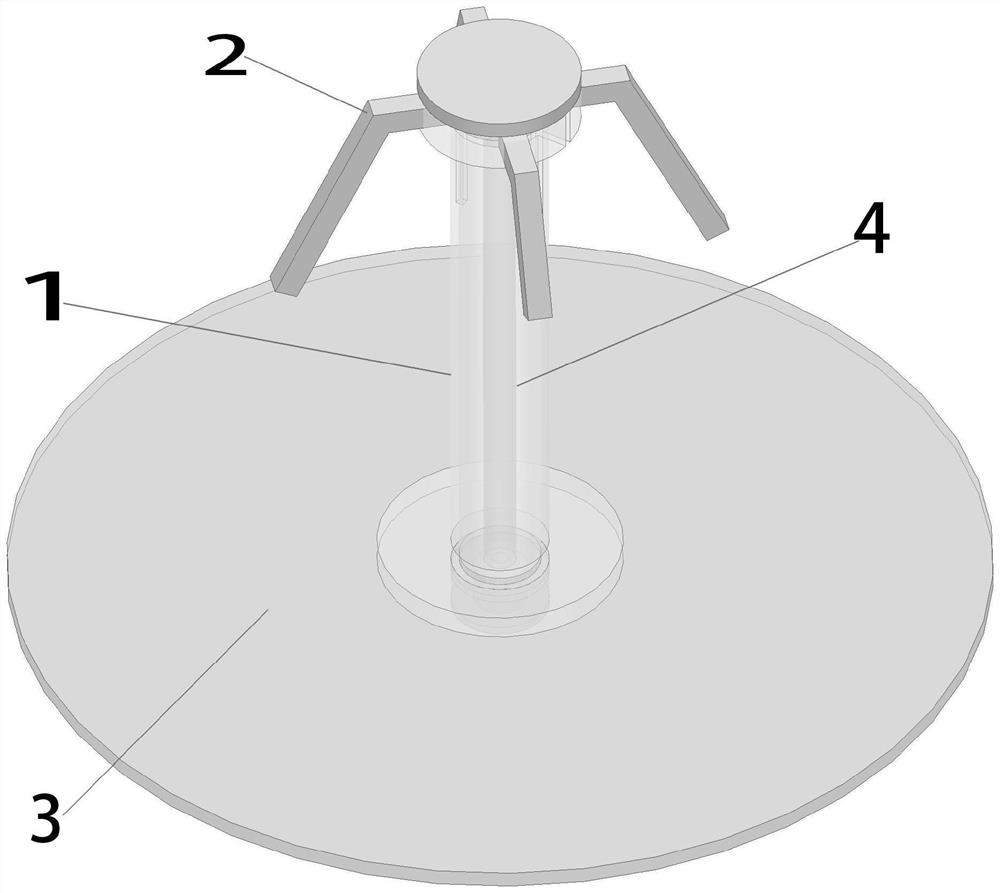
[0024] Such as figure 1 As shown, a 50° circularly polarized cone beam antenna with a frequency of 2.15GHz includes a cylindrical support structure 1, an arm 2 arranged at the top of the cylindrical support structure, and a reflector 3 arranged at the bottom end of the cylindrical support structure. The cylindrical support structure includes inner and outer layers, and a feeder line 4 is arranged inside, and the reflection plate is a disc filled with distilled water.

[0025] In a further embodiment, the outrigger arms are divided into two groups, and the outrigger arms in the same group are arranged directly opposite to each other. The outrigger arms include horizontal columns and inclined columns, and the total length of the horizontal columns is 10mm. The length of the column inserted in the horizontal direction is 3mm, and the length of one set of inclined columns with outstretched arms is 28mm, and the length of the other set of inclined columns with outstretched arms is 18m


PUM

PropertyMeasurementUnit
Lengthaaaaaaaaaa
Radiusaaaaaaaaaa
The inside diameter ofaaaaaaaaaa

Abstract

The invention discloses a 50-degree circularly polarized conical beam antenna with 2.15 GHz frequency, which comprises a cylindrical support structure, a support arm arranged at the top end of the cylindrical support structure and a reflection disc arranged at the bottom end of the cylindrical support structure, the cylindrical support structure comprises an inner layer and an outer layer, a feed circuit is arranged in the cylindrical support structure, and the reflection disc is a disc containing distilled water. The antenna is simple in structure, proper in size, proper in working frequency, large in angle, high in gain and convenient for later design and debugging.

Description


Claims


Application Information

Patent Timeline
Owner NANJING UNIV OF SCI & TECH
Why Eureka
Try Eureka