Optical non-uniformity compensation (NUC) for passive imaging sensors using micro-electro-mechanical system (MEMS) micro-mirror arrays (MMAS)

a technology of optical non-uniformity compensation and imaging sensor, which is applied in the field of non-uniformity compensation (nuc) for passive imaging sensors, can solve the problems of fixed pattern noise, non-uniformity that exists in imaging sensors that must be corrected, and non-uniformity in the response of individual pixels. it is not easy to change the fixed pattern noise with tim

Active Publication Date: 2022-09-29
RAYTHEON CO
View PDF3 Cites 0 Cited by
  • Summary
  • Abstract
  • Description
  • Claims
  • Application Information

AI Technical Summary

Benefits of technology

The technical effect of this patented technology can be explained by its simplification compared with other inventions described earlier on.

Problems solved by technology

Technologies described involve improving the performance of cameras while reducing their size without compromising resolution capabilities. One method involves adding extra components like filters to reduce unwanted background interference caused by ambient lights. Another technique called active mode correction compensates for imperfections in the camera's responses after exposures have been taken into consideration. Additionally, techniques involving periodic updating of these values through electronic control units (ECUs) can help improve overall accuracy even if they don’t perfectly match up between specific points in space.

Method used


Image

  • Optical non-uniformity compensation (NUC) for passive imaging sensors using micro-electro-mechanical system (MEMS) micro-mirror arrays (MMAS)
  • Optical non-uniformity compensation (NUC) for passive imaging sensors using micro-electro-mechanical system (MEMS) micro-mirror arrays (MMAS)
  • Optical non-uniformity compensation (NUC) for passive imaging sensors using micro-electro-mechanical system (MEMS) micro-mirror arrays (MMAS)

Examples


Embodiment Construction

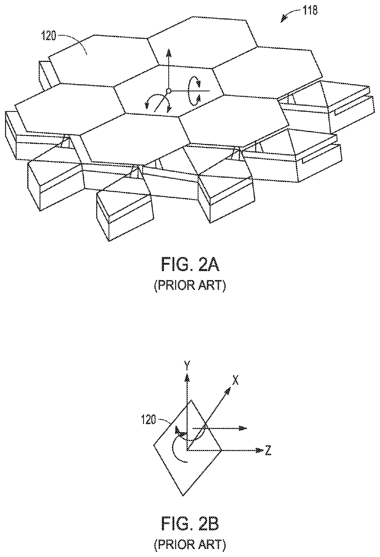
[0021]The present invention provides a passive imaging sensor in which at least one optical element comprises one or more Micro-Electro-Mechanical System (MEMS) Micro-Mirror Arrays (MMAs) including a plurality of independently and continuously controllable mirrors that at least tip and tilt in 2 DOF and may tip, tilt and piston in 3 DOF. In an operational mode, the mirrors are tipped and tilted, and possibly pistoned, such that the optical radiation is focused at the pixelated detector to read out an image of the scene. NUC coefficients such as offset and / or gain are applied to either the output signals of the detector or to the image to form the NUC'd images. In a calibration mode, the mirrors are tipped and tilted and / or pistoned to spatially or temporally blur the image or to re-direct the FOV to one or more on-board calibration sources to generate a uniform image from which to calculate and update the NUC coefficients.

[0022]Referring now to FIGS. 1 and 2A-2B, an embodiment of a


PUM


Abstract

A passive imaging sensor includes a plurality of optical elements in which at least one includes one or more Micro-Electro-Mechanical System (MEMS) Micro-Mirror Arrays (MMAs) having a plurality of independently and continuously controllable mirrors that at least tip and tilt in 2 DOF and may tip, tilt and piston in 3 DOF. In an operational mode, the mirrors are tipped and tilted, and possibly pistoned, such that the optical radiation is focused at the pixelated detector to read out an image of the scene. NUC coefficients such as offset and/or gain are applied to either the output signals of the detector or to the image to form the NUC'd images. In a calibration mode, the mirrors are tipped and tilted and/or pistoned to spatially or temporally blur the image or to re-direct the FOV to one or more on-board calibration sources to generate a uniform image from which to calculate and update the NUC coefficients.

Description


Claims


Application Information

Patent Timeline
Owner RAYTHEON CO
Why Eureka
Try Eureka