Electric power steel pipe milling waste treatment device

A technology for electric steel pipes and waste treatment, applied in the direction of metal processing machinery parts, maintenance and safety accessories, metal processing equipment, etc., can solve problems such as scratches, achieve the effect of easy curling, and improve curling efficiency

Active Publication Date: 2022-04-12
江苏兴齐智能输电科技有限公司
View PDF8 Cites 0 Cited by
  • Summary
  • Abstract
  • Description
  • Claims
  • Application Information

AI Technical Summary

Benefits of technology

This patented technology helps separate longer sections of crushed material like bricks or stones without causing damage during separation process. It uses a special device called a conveyance system to move the materials towards one end before they are cut off into smaller pieces. A guiding rollers help direct the cutting tools along specific paths while collecting any small fragments produced when it separates them. By controllably adjusting the temperature and humidity levels within the chamber, this technique allows for effective cleanup of these types of waste products.

Problems solved by technology

This patented technical problem addressed during the manufacturing process described in the previous paragraph relates to collecting and disposal of large amounts of metallic scrap generated when producing electrical steels due to their unique shape. These scrap often needs to be treated before being reused because it cannot be smoothened without damaging hands on workers' faces.

Method used


Image

  • Electric power steel pipe milling waste treatment device
  • Electric power steel pipe milling waste treatment device
  • Electric power steel pipe milling waste treatment device

Examples


Embodiment 2

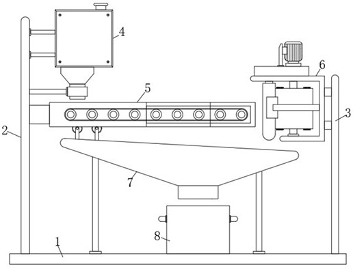
[0043] A method for treating electric steel pipe milling waste, comprising the following steps:

[0044] Step 1: Pour the debris produced in the milling process of the electric steel pipe into the inside of the feeding box 401 through the feeding pipe 402, and the debris inside the feeding box 401 falls on the material guide through the feeding hopper 405 and the feeding pipe 406 On the belt 509, start the material guide motor 505 to drive the leftmost rotating rod 504 to rotate clockwise, and drive all the rotating rods 504 to rotate clockwise synchronously through the transmission assembly 507, and the debris falling on the material guide belt 509 will move from left to right. Conveying on the right;

[0045] Step 2: After the debris leaves the material guide belt 509, the curled debris falls down through the gap between the rotating rod 504 and the rotating rod 504, and the long section of debris continues to be conveyed along with the rotating rod 504, and the material guide

Embodiment 3

[0049] see Figure 9 As shown, the inner wall of the material guide frame 5 is also provided with a processor, and the processor is communicatively connected with a sampling module, a storage module, a temperature monitoring module, a power detection module and a transmission detection module.

[0050] When the curling or separation effect of the debris is not satisfactory, the factors causing the curling or separation effect of the debris are checked one by one through the temperature monitoring module, the power detection module and the transmission detection module.

[0051] After the debris falls in the material receiving box 8, the staff conducts a random inspection of the debris in the material receiving box 8. If the random inspection result is that the debris is unqualified, the sampling module and the processor send a temperature detection signal to the temperature monitoring module. After receiving the temperature detection signal, the temperature monitoring module dete


PUM


Abstract

The invention discloses an electric power steel pipe milling waste treatment device, belongs to the field of electric power steel pipe machining equipment, and is used for solving the problem that long-section-shaped chippings doped in existing milling chippings are prone to scratching the hands of workers, the electric power steel pipe milling waste treatment device comprises a working platform, and a discharging mechanism and a material guiding frame are arranged on the side face, close to a connecting plate, of a mounting plate; according to the device, curled chippings and long-section chippings are separated through the discharging mechanism and the material guiding frame, the chippings fall onto the material guiding belt through the discharging pipe, the chippings are contained and received through the material guiding belt, the chippings are separated through the discharging mechanism and the material guiding frame, the chippings are separated through the discharging pipe, the chippings are separated, and the chippings are stored through the material guiding box. The long-section-shaped chippings are prevented from directly penetrating through the gap between the rotating rods when falling, and after the long-section-shaped chippings are separated from the curled chippings, the long-section-shaped chippings are gathered towards the middle through the gathering section, so that the long-section-shaped chippings are output through the output section with the minimum caliber, and it is guaranteed that the long-section-shaped chippings can be effectively curled.

Description


Claims


Application Information

Patent Timeline
Owner 江苏兴齐智能输电科技有限公司
Why Eureka
Try Eureka