Purification device for discharging dye wastewater
A purification device and dye wastewater technology, which is applied in the direction of water pollutants, chemical instruments and methods, water/sewage multi-stage treatment, etc., can solve the problems of non-colored dye wastewater treatment and reuse, high wastewater treatment costs, loss of dye ratio, etc. problems, to achieve the effect of reducing dye wastewater, reducing treatment costs, and reducing emissions
- Summary
- Abstract
- Description
- Claims
- Application Information
AI Technical Summary
Benefits of technology
Problems solved by technology
Method used
Image

Examples
Embodiment 1
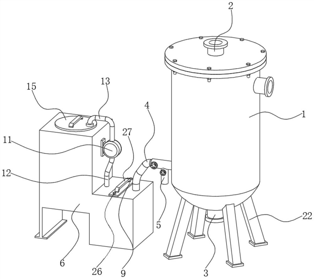
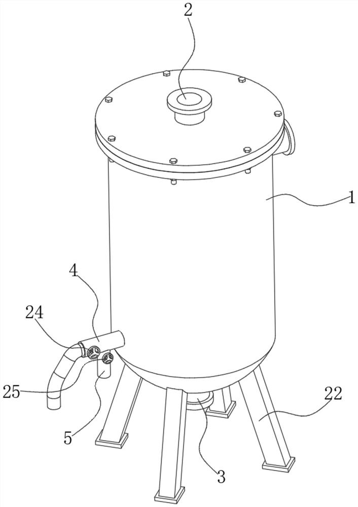
[0026] see Figure 1-6 , the present invention provides a technical solution: a purification device for dye wastewater discharge, comprising a ceramic membrane filter 1 and a treatment box 6, the top of the ceramic membrane filter 1 is connected with a liquid inlet pipe 2, and the bottom of the ceramic membrane filter 1 The concentrated liquid outlet pipe 3 is connected, the bottom of the ceramic membrane filter 1 close to the treatment tank 6 is connected with the first permeate outlet pipe 4, and the bottom of the first permeate outlet pipe 4 is connected with the second permeate outlet pipe 4. A first valve 24 is arranged inside the first permeate outlet pipe 4, a second valve 25 is arranged inside the second permeate outlet pipe 5, and one end of the treatment tank 6 is opened. There is a first processing chamber 7, the end of the first permeate outlet pipe 4 away from the ceramic membrane filter 1 is connected to the first processing chamber 7, the inside of the first proces
Embodiment 2
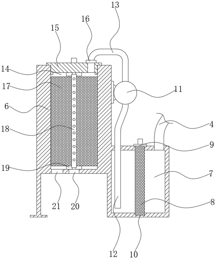
[0029] Such as Figure 1-6As shown, on the basis of Embodiment 1, the present invention provides a technical solution: the top of the adsorption layer 8 is fixedly installed with a mounting plate 9, and the inside of both ends of the mounting plate 9 are sleeved with fixing bolts 26, and the mounting plate 9 is fixed by The bolt 26 is fixed on the top of the processing box 6, the top of the mounting plate 9 is fixedly equipped with a handle 27, the inside of the first processing chamber 7 is provided with a U-shaped mounting groove 10, and the U-shaped mounting groove 10 is compatible with the size of the adsorption layer 8 match.
[0030] In this embodiment, the adsorption layer 8 is located inside the U-shaped installation groove 10 through the provided installation plate 9 and the U-shaped installation groove 10, and then the adsorption layer 8 is pushed down so that the adsorption layer 8 is completely located in the first processing chamber 7 After the inside, utilize fixin
Embodiment 3
[0032] Such as Figure 1-6 As shown, on the basis of Embodiment 1 and Embodiment 2, the present invention provides a technical solution: a connection seat 16 is fixedly installed at one end of the top of the sealing cover 15, and the end of the output pipe 13 away from the extraction pump 11 is threadedly connected to the connection seat 16 , one end inside the sealing cover 15 is provided with a connection groove 23 , and the connection groove 23 communicates with the connection seat 16 .
[0033] In this embodiment, by threading the output pipe 13 with the connection seat 16, the output pipe 13 and the connection seat 16 are detachably connected, and the output pipe 13 and the sealing cover 15 are disassembled, so that the sealing cover can be easily removed. 15 is removed, and after one end of the output pipe 13 is connected to the connection seat 16 through the connecting groove 23 provided, the permeate in the output pipe 13 flows into the second processing chamber 14 throug
PUM
 Abstract
Description
Claims
Application Information
 - R&D Engineer
- R&D Manager
- IP Professional
- Industry Leading Data Capabilities
- Powerful AI technology
- Patent DNA Extraction
Browse by: Latest US Patents, China's latest patents, Technical Efficacy Thesaurus, Application Domain, Technology Topic.
© 2024 PatSnap. All rights reserved.Legal|Privacy policy|Modern Slavery Act Transparency Statement|Sitemap