Biological membrane tissue optical detection cutting method and system based on weak coherent interference

A technology of optical detection and cutting method, which is applied in the direction of using optical devices, measuring devices, instruments, etc., and can solve the problems that the thickness affects the normal function of artificial heart valves, etc.

Pending Publication Date: 2022-04-12
浙江大学嘉兴研究院 +1
View PDF0 Cites 0 Cited by
  • Summary
  • Abstract
  • Description
  • Claims
  • Application Information

AI Technical Summary

Problems solved by technology

Additionally, this need is even more important for placement of compressible/expandable prosthetic heart valves

Method used


Image

  • Biological membrane tissue optical detection cutting method and system based on weak coherent interference
  • Biological membrane tissue optical detection cutting method and system based on weak coherent interference
  • Biological membrane tissue optical detection cutting method and system based on weak coherent interference

Examples


Embodiment Construction

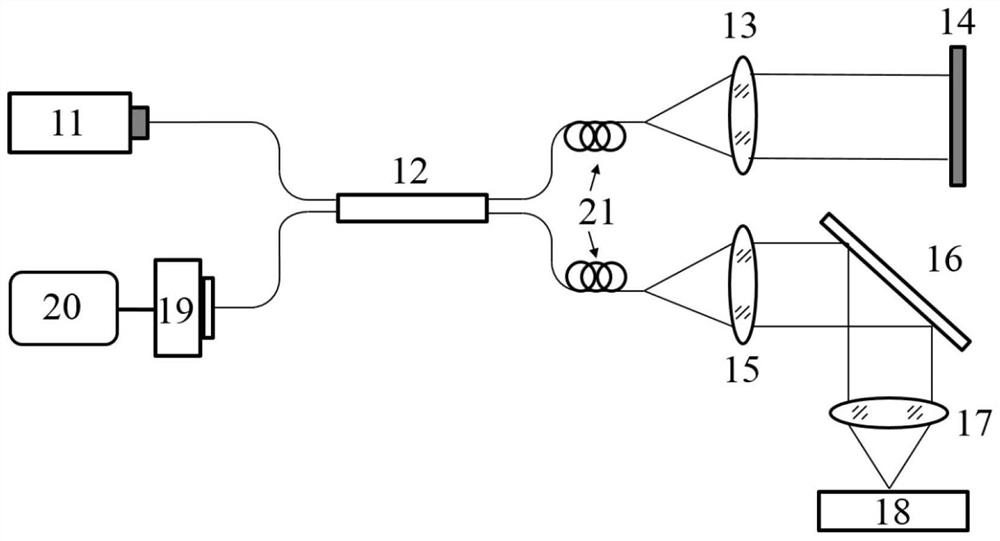
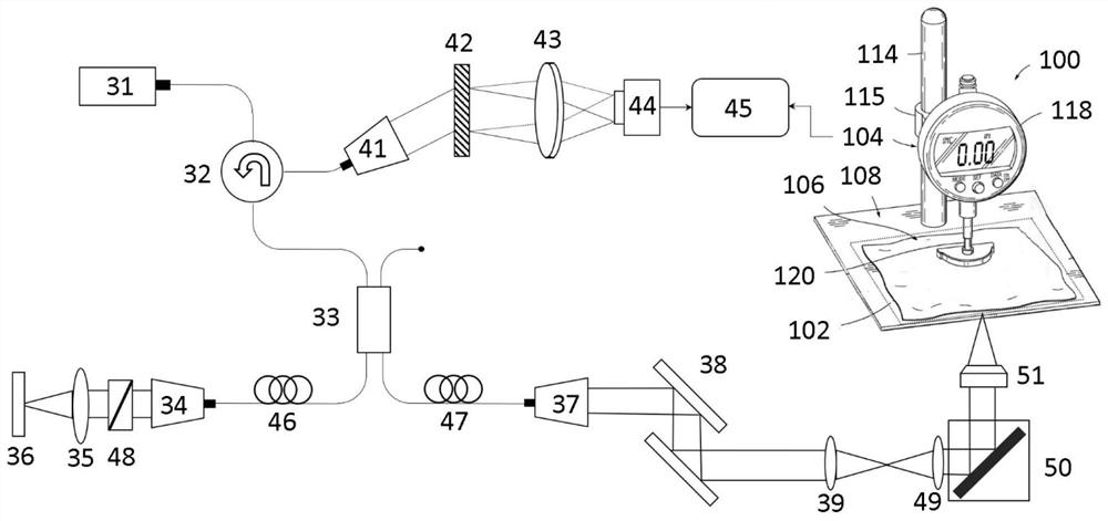
[0055] Specific embodiments of the present invention will be described in detail below in conjunction with the accompanying drawings, which form a part of this document. It should be noted that these descriptions and examples are illustrative only, and should not be construed as limiting the scope of the present invention. The protection scope of the present invention is defined by the appended claims, and any changes based on the claims of the present invention All are protection scope of the present invention.

[0056] In order to facilitate the understanding of the embodiments of the present invention, each operation is described as a plurality of discrete operations, however, the order of description does not represent the order in which the operations are performed.

[0057] In this description, the x-y-z three-dimensional coordinate representation based on the spatial direction is used for the sample measurement space. This description is provided merely to facilitate disc


PUM


Abstract

The invention discloses a biological membrane tissue optical detection cutting method and system based on weak coherence interference. A die cutting assembly is placed above the biological tissue, and a biological membrane tissue is placed in the die cutting assembly; detecting the thickness of the target area of the biological membrane tissue through the die cutting assembly by using an optical coherence imaging (OCT) system; based on the thickness of the target area of the biological membrane tissue, a mold in a mold cutting assembly is controlled to cut the target area to obtain the artificial heart bioprosthetic valve leaflet. According to the invention, the micrometer precision and non-contact measurement of the thickness of the biofilm tissue can be realized, and the cutting of the artificial heart biovalve leaflets with uniform thickness can be realized quickly.

Description


Claims


Application Information

Patent Timeline
Owner 浙江大学嘉兴研究院
Why Eureka
Try Eureka