Semi-automatic electronic chip visual inspection equipment

An electronic chip, visual inspection technology, applied in measuring devices, material analysis by optical means, instruments, etc., can solve the problems of inaccurate inspection results, chip surface errors, inconvenient use, etc., and achieve the effect of accurate inspection results.

Pending Publication Date: 2022-04-12
GUANGDONG POLYTECHNIC NORMAL UNIV
View PDF0 Cites 0 Cited by
  • Summary
  • Abstract
  • Description
  • Claims
  • Application Information

AI Technical Summary

Problems solved by technology

[0003] The existing technology does not clean the surface of the chip before the visual inspection of the chip, which will easily cause errors in the judgment of the visual inspection

Method used


Image

  • Semi-automatic electronic chip visual inspection equipment
  • Semi-automatic electronic chip visual inspection equipment

Examples


Example Embodiment

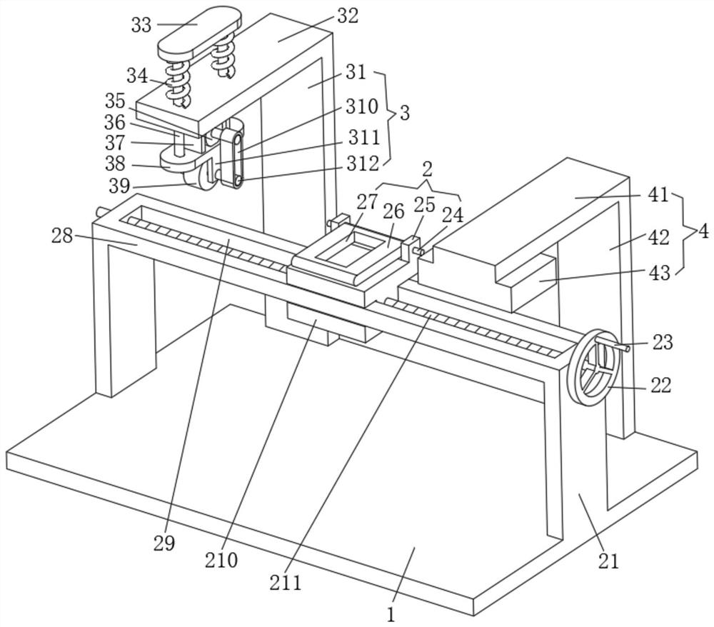
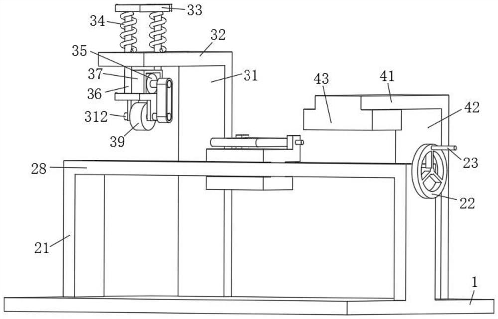
[0023] Next, the technical solutions in the embodiments of the present invention will be described in connection with the drawings of the embodiments of the present invention, and it is understood that the described embodiments are merely the embodiments of the present invention, not all of the embodiments. Based on the embodiments of the present invention, all other embodiments obtained by those of ordinary skill in the art are in the range of the present invention without making creative labor premise.

[0024] See Figure 1-2 This embodiment provides a technical solution: a semi-automatic electronic chip visual detection device, including a bottom plate 1, an electronic chip fixing unit 2, a chip surface cleaning unit 3, and a visual detection unit 4;

[0025] Backplane 1: is a rectangular;

[0026] Electronic chip fixing unit 2: includes a vertical support plate 12, a rotating shaft one 24, a support ear, a movable plate 26, a rectangular pass groove 27, a rectangular fixing plate


PUM


Abstract

The invention discloses semi-automatic electronic chip visual inspection equipment, which relates to the technical field of chip visual inspection and comprises a bottom plate, an electronic chip fixing and moving unit, a chip surface cleaning unit and a visual inspection unit. The bottom plate is rectangular; the electronic chip fixing and moving unit comprises first vertical supporting plates, first rotating shafts, first supporting lugs, movable plates, rectangular through grooves, first rectangular fixing plates, rectangular sliding grooves, I-shaped sliding blocks and screw rods, and the two ends of the middle of the upper surface of the bottom plate are fixedly connected with the lower ends of the two correspondingly-matched first vertical supporting plates correspondingly; the side faces of the upper ends of the two first vertical supporting plates are fixedly connected with the side faces of the two ends of a first rectangular fixing plate correspondingly, and a rectangular sliding groove is formed in the middle of the upper surface of the first rectangular fixing plate. Before visual inspection is carried out on the chip, the surface of the chip can be cleaned, so that smudginess on the surface of the chip does not cause errors to judgment of visual inspection, and the detection result is more accurate.

Description


Claims


Application Information

Patent Timeline
Owner GUANGDONG POLYTECHNIC NORMAL UNIV
Why Eureka
Try Eureka