Metal cutting equipment for manufacturing computer radiator

A metal cutting and radiator technology, applied in other manufacturing equipment/tools, manufacturing tools, etc., can solve problems such as low cutting efficiency and cumbersome processes, and achieve the effect of improving work efficiency, shortening time, and eliminating grinding processes

Pending Publication Date: 2022-04-22
重庆财经学院
View PDF21 Cites 0 Cited by
  • Summary
  • Abstract
  • Description
  • Claims
  • Application Information

AI Technical Summary

Benefits of technology

The invention improves the performance of machining operations for metals with multiple tools used together. It achieves this through dual-servo systems where one system moves at least one tool while another pulls it further away from other tools or uses only one type of movement. This allows more efficient use of space during processing compared to traditional methods like single screw machines without sacrifices accuracy. Additionally, there may also include an abrasive pad attached between the machine's housing and its moving parts to improve smoothness when finishing surfaces such as steel plates. Overall, these technical improvements enhance the overall quality and productivity of manufactured products made from materials processed under specific conditions.

Problems solved by technology

This patented technology describes how computers have become more reliable over time due to their ability to handle complex workings faster than before they start working properly or being replaced quickly if damaged. To solve these issues, there has been developed an improved method called Metal Material Grinding (MGM). It involves moving away from traditional methods like saw blades towards machines that use lasers instead of wire brushes to remove unwanted metallic substances. These improvements make MGI easier and less expensive compared to older ways of removing them.

Method used


Image

  • Metal cutting equipment for manufacturing computer radiator
  • Metal cutting equipment for manufacturing computer radiator
  • Metal cutting equipment for manufacturing computer radiator

Examples


Embodiment

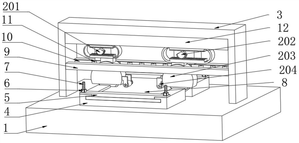
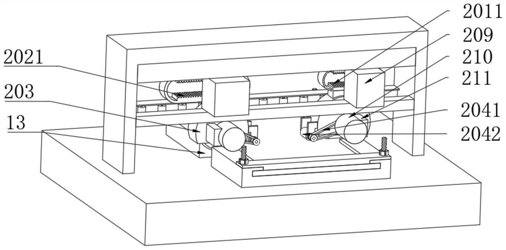
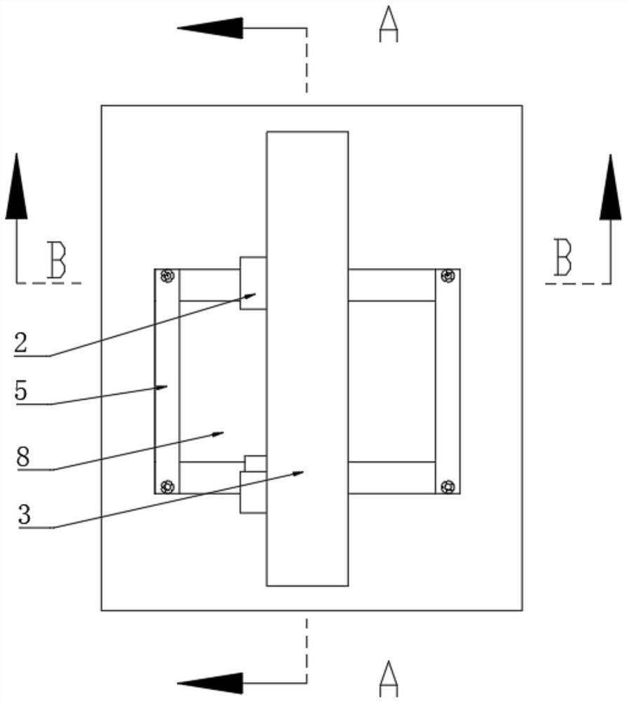
[0030] Such as Figure 1-6 As shown, a metal cutting device for the manufacture of computer radiators includes a workbench 1, a placement table 4 is fixedly installed on the upper surface of the workbench 1, and a metal plate 8 is fixedly placed inside the placement table 4 through a pressure plate 5. The workbench 1 A gantry 3 is installed on the upper surface and across the placing table 4. A cutting assembly 2 is arranged inside the gantry 3. The cutting assembly 2 includes a first driving structure 201 and a second driving structure 202. The first driving structure 201 and the second driving structure 202 are respectively driven by two first servo motors 208, the first drive structure 201 and the bottom end of the first drive structure 201 are respectively fixedly connected with a protective cover 203 through a fixed block 206, and the inside of the protective cover 203 is rotated by a second servo motor 210. The cutter 207 is provided with a grinding assembly 204 on the oppo


PUM


Abstract

The invention provides metal cutting equipment for computer radiator manufacturing, and relates to the technical field of computer radiator machining, the metal cutting equipment comprises a workbench, a placing table is fixedly mounted on the upper surface of the workbench, a metal plate is fixedly placed in the placing table through a pressing plate, and a portal frame is mounted on the upper surface of the workbench and stretches across the placing table; a cutting assembly is arranged in the portal frame, the cutting assembly comprises a first driving structure and a second driving structure, protective covers are fixedly connected to the bottom ends of the first driving structure and the second driving structure through fixing blocks correspondingly, and cutting knives are rotationally arranged in the protective covers through second servo motors; and a grinding assembly is arranged on the opposite sides of the two protective covers, by arranging the cutting assembly, the two cutting knives can move at the same time and conduct cutting at different distances, by arranging the grinding assembly, the cutting surfaces can be ground when the cutting knives reset, and therefore the working efficiency can be improved to a large extent.

Description


Claims


Application Information

Patent Timeline
Owner 重庆财经学院
Why Eureka
Try Eureka