Laser radar calibration method and device, electronic equipment and storage medium

A technology of laser radar and calibration method, which is applied to radio wave measurement systems and instruments, can solve the problems of high calibration cost, low calibration efficiency, and low calibration accuracy, and achieve the effect of improving calibration efficiency and saving calibration cost

Pending Publication Date: 2022-05-13
WUHAN UNIV OF TECH
View PDF0 Cites 1 Cited by
  • Summary
  • Abstract
  • Description
  • Claims
  • Application Information

AI Technical Summary

Benefits of technology

This patented technology allows for quick and efficient calibration (requiring no external markers) of an autonomous vehicle's LiDAR sensor used during navigation. By comparing different points from both sensors, we aimed at finding their best match based upon these measurements. These optimal settings were determined through optimization algorithms that optimize the placement of Lidars within the environment around it. Overall, this innovation provides technical benefits such as improved accuracy over time, reduced costs associated with manually setting up environmental markings, etc., which could lead to more accurate navigational capabilities for vehicles.

Problems solved by technology

This patents describes different techniques for improving the performance of LADARs by aligning their internal measurements from various sources like cameras or lens units. However, current solutions require expensive equipment and complicated processes which limit usability options.

Method used


Image

  • Laser radar calibration method and device, electronic equipment and storage medium
  • Laser radar calibration method and device, electronic equipment and storage medium
  • Laser radar calibration method and device, electronic equipment and storage medium

Examples


Embodiment Construction

[0038] Preferred embodiments of the present invention will be described in detail below in conjunction with the accompanying drawings, wherein the accompanying drawings constitute a part of the application and together with the embodiments of the present invention are used to explain the principle of the present invention and are not intended to limit the scope of the present invention.

[0039] The present invention provides a laser radar calibration method, device and computer-readable storage medium, which are described in detail below:

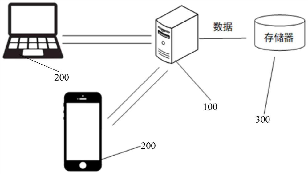
[0040] An embodiment of the present invention provides an application system of a lidar calibration method, figure 1 It is a schematic diagram of the scene of an embodiment of the application system of the laser radar calibration method provided by the present invention. The system may include a server 100, and a laser radar calibration device is integrated in the server 100, such as figure 1 server in .

[0041] In the embodiment of the pre


PUM


Abstract

The invention discloses a laser radar calibration method and apparatus, an electronic device and a storage medium. The method comprises the steps of obtaining point cloud data of a reference laser radar and a to-be-calibrated laser radar for the same scene; matching the point cloud data acquired by the reference laser radar and the to-be-calibrated laser radar to obtain coordinates of the reference laser radar in a to-be-calibrated laser radar coordinate system; according to the coordinate of the reference laser radar in the coordinate system of the to-be-calibrated laser radar, the absolute coordinate of the reference laser radar in the world coordinate system, the initial installation parameter of the to-be-calibrated laser radar relative to the inertial measurement unit, and the pose of the inertial measurement unit in the world coordinate system when the to-be-calibrated laser radar obtains scene point cloud data; solving optimized installation parameters of the to-be-calibrated laser radar relative to the inertial measurement unit; and calibrating the to-be-calibrated laser radar. According to the method, the rapid calibration of the dynamic laser radar platform is realized under the condition of not depending on manual preset environment feature marks.

Description


Claims


Application Information

Patent Timeline
Owner WUHAN UNIV OF TECH
Why Eureka
Try Eureka