Backflushing shell-and-tube heat exchanger
A heat exchanger and tube flushing technology is applied in the field of backflushing shell and tube heat exchangers, which can solve the problems of complicated operation, poor cleaning effect, time-consuming and laborious operation, etc., and achieve the effect of improving cleaning efficiency.
- Summary
- Abstract
- Description
- Claims
- Application Information
AI Technical Summary
Benefits of technology
Problems solved by technology
Method used
Image

Examples
Embodiment 1
[0031] The technical solutions employed in the present invention are as follows:
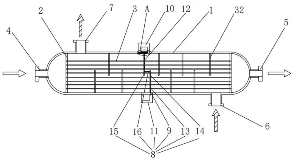
[0032] as Figure 1As shown, the present invention discloses a recoil tube shell type heat exchanger, comprising: a tank 1, the tank at both ends of the partition plate 2, two separators separate the tank into three independent chambers, the separator plate is provided with a plurality of heat transfer tubes 3, the tank at both ends are provided with a coolant inlet pipe 4 and a coolant outlet pipe 5; located in the middle of the cavity are respectively provided with a material inlet pipe 6 and a material outlet pipe 7; the middle of the cavity is equipped with a cleaning mechanism 8, The cleaning mechanism for automatically cleaning the cavity into the material according to the temperature and flow rate of the cleaning liquid.
Embodiment 2
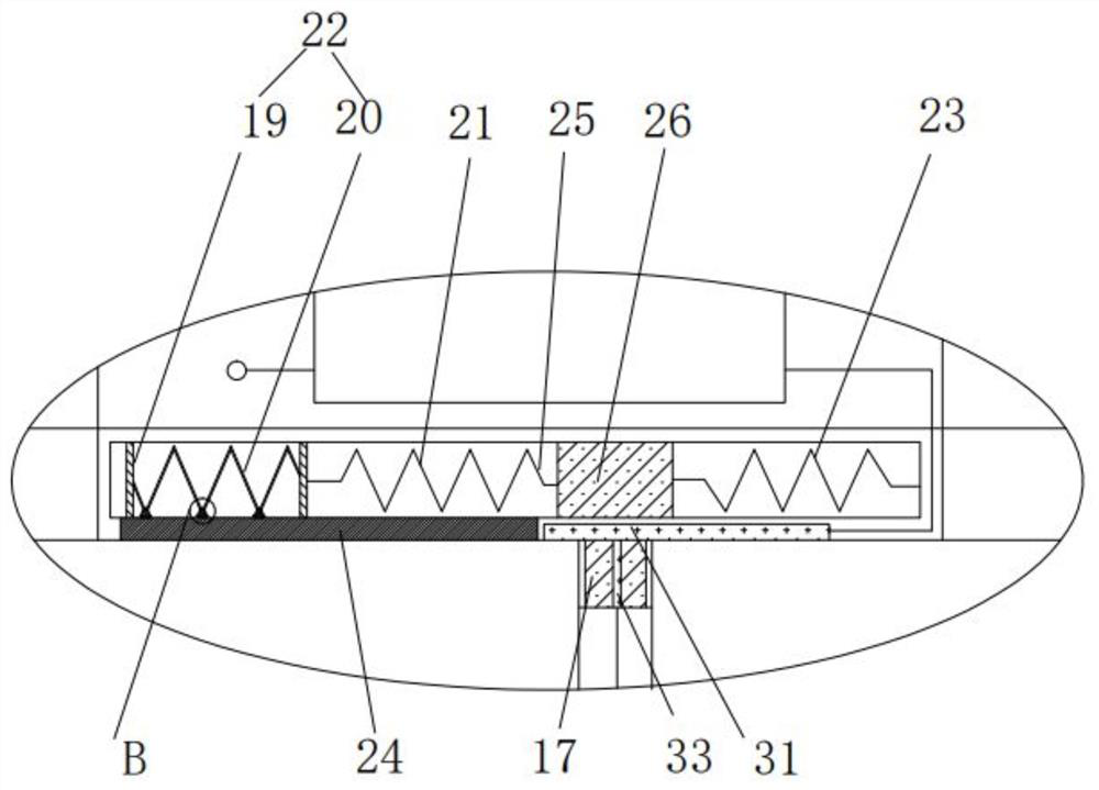
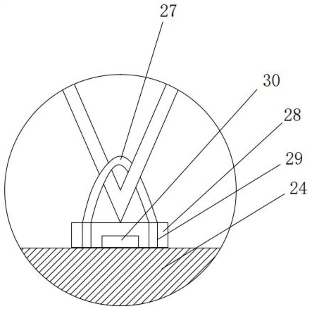
[0034] as Figure 2 、 Figure 3 、 Figure 4 and Figure 5 As shown, the present invention further discloses a recoil tube shell type heat exchanger, comprising: a tank, the tank at both ends of the partition plate, two separators separate the tank into three independent chambers, the separator plate is provided with a plurality of heat transfer tubes, the tank at both ends are provided with coolant inlet pipe and coolant outlet pipe; located in the middle of the cavity are provided with material inlet pipe and material outlet pipe; the middle of the cavity is equipped with a cleaning mechanism, the cleaning mechanism for automatically cleaning the cavity into the material according to the temperature and flow of the cleaning liquid.
[0035] There are multiple barrier plates 32 in the cavity located in the middle, and the two adjacent barrier plates are located on the upper and lower sides of the cavity. The cleaning mechanism comprises a first box 10 and a second box 11 located on both
PUM
 Abstract
Description
Claims
Application Information
 - R&D Engineer
- R&D Manager
- IP Professional
- Industry Leading Data Capabilities
- Powerful AI technology
- Patent DNA Extraction
Browse by: Latest US Patents, China's latest patents, Technical Efficacy Thesaurus, Application Domain, Technology Topic.
© 2024 PatSnap. All rights reserved.Legal|Privacy policy|Modern Slavery Act Transparency Statement|Sitemap