Test tube identification method and system, electronic equipment and medium

A recognition method and test tube technology, applied in the field of image recognition, can solve problems such as failure to identify test tubes and achieve accurate recognition

Pending Publication Date: 2022-05-31
CHONGQING MICRO IDENTIFICATION TECH
View PDF0 Cites 0 Cited by
  • Summary
  • Abstract
  • Description
  • Claims
  • Application Information

AI Technical Summary

Benefits of technology

This invention describes an apparatus that uses image processing techniques to identify specific areas on a sample container or other object being tested by capturing images from different angles around it. By comparing results with previous data points, this system can help determine if there are any defects present within these areas without actually testing them themselves.

Problems solved by technology

This technical problem addressed by this patented technology relates to improving the accuracy with which healthcare workers can verify that all their sample containers are properly placed onto patient-related equipment for diagnosis or therapy purposes without leaving any empty ones behind due to lacking them afterward.

Method used


Image

  • Test tube identification method and system, electronic equipment and medium
  • Test tube identification method and system, electronic equipment and medium
  • Test tube identification method and system, electronic equipment and medium

Examples


Embodiment Construction

[0047] Embodiments of the present invention are described below through specific examples, and those skilled in the art can easily understand other advantages and effects of the present invention from the content disclosed in this specification. The present invention can also be implemented or applied through other different specific implementation modes, and various modifications or changes can be made to the details in this specification based on different viewpoints and applications without departing from the spirit of the present invention. It should be noted that, in the case of no conflict, the following embodiments and features in the embodiments can be combined with each other.

[0048] It should be noted that the diagrams provided in the following embodiments are only schematically illustrating the basic ideas of the present invention, and only the components related to the present invention are shown in the diagrams rather than the number, shape and shape of the componen


PUM


Abstract

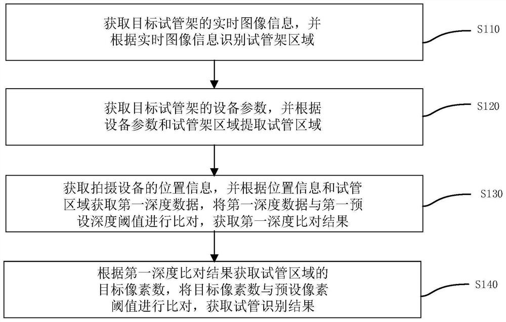
The invention is suitable for the technical field of image recognition, and provides a test tube recognition method and system, electronic equipment and a medium, and the method comprises the steps: obtaining the real-time image information of a target test tube rack, and recognizing a test tube rack region according to the real-time image information, a test tube being placed on the target test tube rack; acquiring equipment parameters of the target test tube rack, and extracting a test tube region according to the equipment parameters and the test tube rack region; acquiring position information of the shooting equipment, acquiring first depth data according to the position information and the test tube area, and comparing the first depth data with a first preset depth threshold to acquire a first depth comparison result; obtaining a target pixel number of the test tube area according to the first depth comparison result, and comparing the target pixel number with a preset pixel threshold to obtain a test tube identification result; by adopting the method, the problem that the test tube omission cannot be accurately identified in the prior art is solved.

Description


Claims


Application Information

Patent Timeline
Owner CHONGQING MICRO IDENTIFICATION TECH
Why Eureka
Try Eureka