Welding tool for airflow plate and hook of turbojet engine

A turbojet engine and welding tooling technology, which is applied in the aviation field, can solve the problems of easy deformation of the airflow plate and warping of the airflow plate during the cooling process

Active Publication Date: 2022-07-15
江西中发天信航空发动机科技有限公司
View PDF6 Cites 0 Cited by
  • Summary
  • Abstract
  • Description
  • Claims
  • Application Information

AI Technical Summary

Benefits of technology

This new design allows an aircraft's main fan nozzle plates or other components like fuel pumps can be easily connected with another component without causing damage during assembly due to their shape changes caused by heat generated from laser beam melting processes. By supporting this part through bases and fixing certain positions, there will remain stable connections between these parts even if they experience thermal expansion issues over time.

Problems solved by technology

The technical problem addressed by this patented method for repairing damaged parts on gas turbine engines caused by thermal stress or other factors that cause it's shape changes over time can be related to improving its durability against damage due to these conditions without compromising their performance.

Method used


Image

  • Welding tool for airflow plate and hook of turbojet engine
  • Welding tool for airflow plate and hook of turbojet engine
  • Welding tool for airflow plate and hook of turbojet engine

Examples


Embodiment Construction

[0031] The following describes in detail the embodiments of the present invention, examples of which are illustrated in the accompanying drawings, wherein the same or similar reference numerals refer to the same or similar elements or elements having the same or similar functions throughout. The embodiments described below with reference to the accompanying drawings are exemplary, and are intended to explain the present invention and should not be construed as limiting the present invention.

[0032] In the description of the present invention, it should be understood that the terms "length", "width", "upper", "lower", "front", "rear", "left", "right", "vertical", The orientations or positional relationships indicated by "horizontal", "top", "bottom", "inside", "outside", etc. are based on the orientations or positional relationships shown in the accompanying drawings, which are only for the convenience of describing the present invention and simplifying the description, rather th


PUM


Abstract

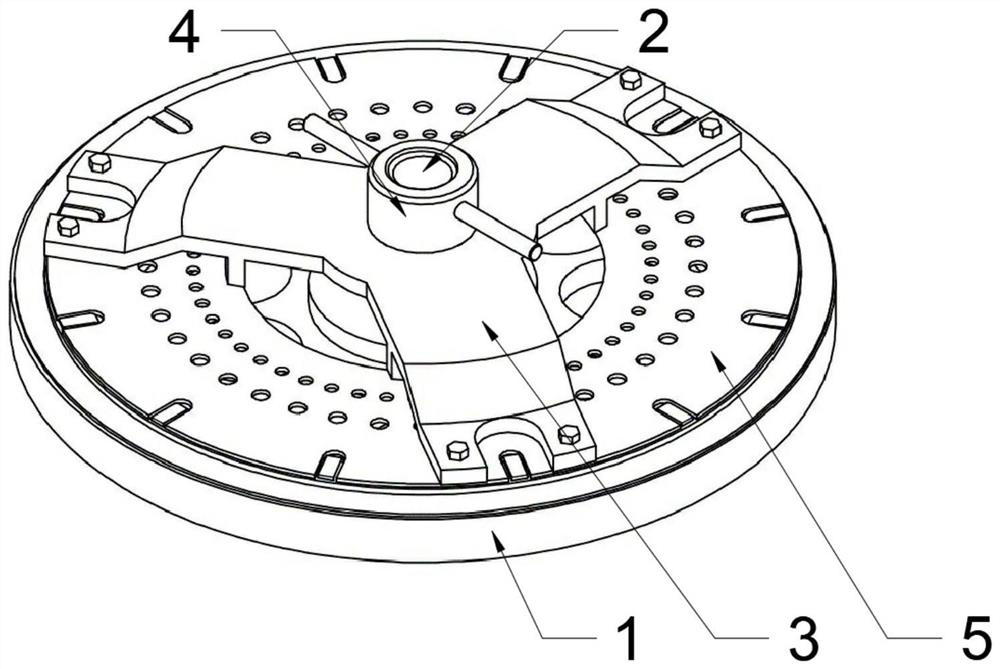
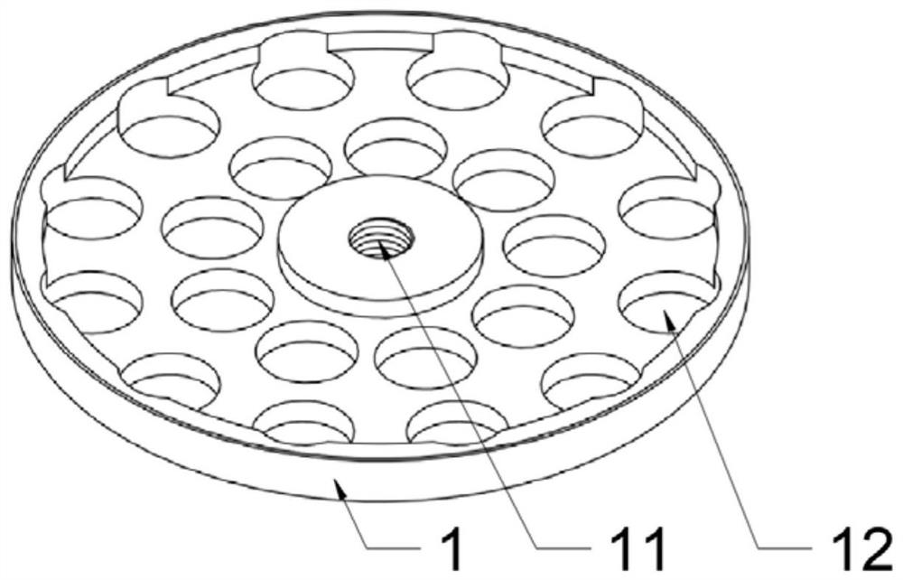
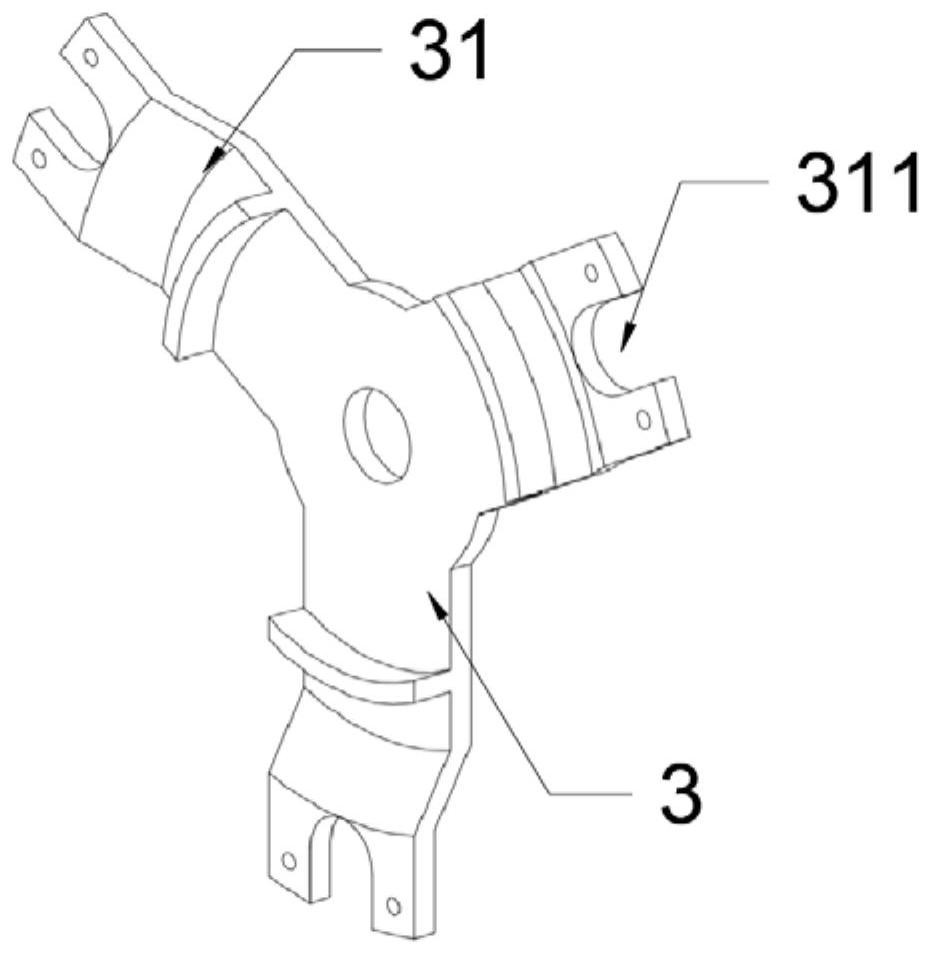
According to the welding tool for the airflow plate and the hook of the turbojet engine, the base is adopted to support the airflow plate, the locking screw is arranged on the base, the welding position of the airflow plate is fixed above the airflow plate through the pressing plate and the locking nut (the locking nut is matched with the locking screw, and the airflow plate can be fixed by rotating the locking nut, so that the airflow plate can be fixed. The locking nut is arranged on the pressing plate, so that the locking nut applies downward pressure to the pressing plate, and then the pressing plate presses the airflow plate below, so that when the airflow plate is subjected to hook welding, the airflow plate is pressed by the pressing plate, deformation such as edge curling is not prone to occurring, and then it is guaranteed that after the hook welding procedure of the airflow plate is completed, the appearance size of the airflow plate is basically kept unchanged.

Description


Claims


Application Information

Patent Timeline
Owner 江西中发天信航空发动机科技有限公司
Why Eureka
Try Eureka