Body movement state monitoring method and monitoring device
A monitoring device and status technology, applied in diagnostic recording/measurement, medical science, diagnosis, etc., can solve problems such as inconvenient detection, affecting user's sleep quality, affecting user's normal activities, etc., and achieves the effect of low cost
- Summary
- Abstract
- Description
- Claims
- Application Information
AI Technical Summary
Problems solved by technology
Method used
Image

Examples
Embodiment 1
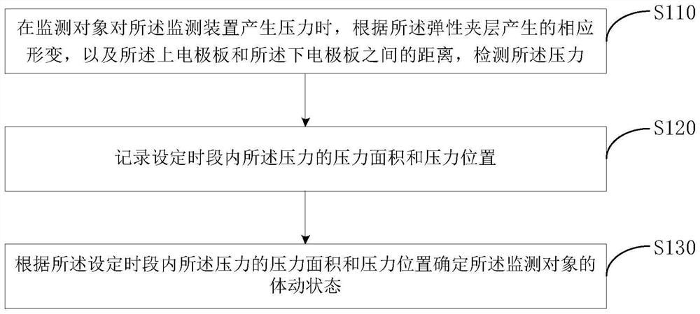
[0040] figure 1 This is a schematic flowchart of a body movement state monitoring method provided in Embodiment 1 of the present invention. This embodiment can be applied to a situation in which the body movement state of a monitoring object is detected in a sleep state. The method can be executed by a monitoring device. The monitoring device It includes: a chip, an upper electrode plate, an elastic interlayer and a lower electrode plate, and the monitoring device can be configured in items such as mattresses that are convenient for human use. like figure 1 As shown, the method includes:
[0041] S110. When the monitoring object exerts pressure on the monitoring device, detect the pressure according to the corresponding deformation of the elastic interlayer and the distance between the upper electrode plate and the lower electrode plate.
[0042] Among them, the elastic interlayer of the monitoring device can be made of elastic materials, such as sponge, etc., and the upper ele
Embodiment 2
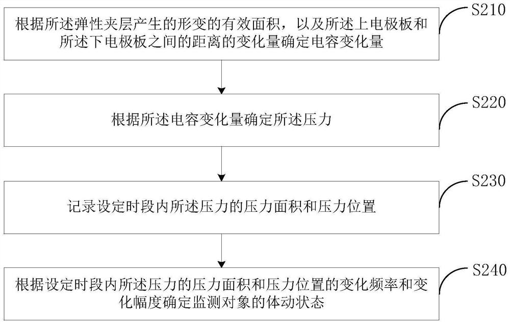
[0060] figure 2 This is a schematic flowchart of a body motion state monitoring method provided in Embodiment 2 of the present invention, and Embodiment 2 is refined on the basis of the foregoing embodiments. In this embodiment, the process of determining the body motion state of the monitoring object according to the pressure area and pressure position of the pressure within the set time period is described in detail. It should be noted that, for technical details not described in detail in this embodiment, reference may be made to any of the foregoing embodiments.
[0061] like figure 2 As shown, the method includes:
[0062] S210. Determine the capacitance change amount according to the effective area of the deformation generated by the elastic interlayer and the change amount of the distance between the upper electrode plate and the lower electrode plate.
[0063] Among them, when the monitoring object is lying on the bed with the built-in monitoring device, the elasti
Embodiment 3
[0093] Figure 4 This is a schematic structural diagram of a monitoring device provided in Embodiment 3 of the present invention. like Figure 4 As shown, the device includes: a chip 40, an upper electrode plate 41, an elastic interlayer 42 and a lower electrode plate 43;
[0094] The upper electrode plate 41 and the lower electrode plate 43 are made of flexible or elastic conductive materials, the upper electrode plate 41 and the lower electrode plate 43 are arranged opposite to each other, and at least one of the upper electrode plate 41 and the lower electrode plate 43 contains multiple pieces of conductive material for collecting multiple signals;
[0095] When the monitoring object exerts pressure on the monitoring device, the elastic interlayer 42 is correspondingly deformed, and the distance between the upper electrode plate 41 and the lower electrode plate 43 is correspondingly changed;
[0096] The chip 40 is used to detect the pressure according to the corresponding
PUM
 Abstract
Description
Claims
Application Information
 - R&D Engineer
- R&D Manager
- IP Professional
- Industry Leading Data Capabilities
- Powerful AI technology
- Patent DNA Extraction
Browse by: Latest US Patents, China's latest patents, Technical Efficacy Thesaurus, Application Domain, Technology Topic.
© 2024 PatSnap. All rights reserved.Legal|Privacy policy|Modern Slavery Act Transparency Statement|Sitemap