Fence mesh plate and fence system with fence mesh plate

A fence mesh and mesh surface technology, which is applied in the direction of fences, building types, buildings, etc., can solve the problems of non-exposed mesh surface protection, low installation efficiency, and high work intensity, achieving low work intensity, high installation efficiency, and ease of use. High safety effect

Active Publication Date: 2022-07-29
VICHNET COMM SCI & TECH
View PDF6 Cites 0 Cited by
  • Summary
  • Abstract
  • Description
  • Claims
  • Application Information

AI Technical Summary

Benefits of technology

This patented technology describes an improved security barrier system for temporary structures such as road signs. It includes columns made up of multiple cylinders joined together along their edges. These bars have different sizes depending upon how they should fit within certain dimensions. They may include padding material around them if needed. There're also some embodiments where these systems provide extra strength while still being easy to operate safely. Additionally, the design allows for efficient mounting and removal of the existing barriers. Overall, these technical improvements improve the performance and convenience of the barrier systems.

Problems solved by technology

This technical problem addressed in this patented text relating to safety concerns during installing conventional fencing systems involves the lengthy time required when cutting off the mesh board or adding extra parts like corner guards around its perimeter. Additionally, current methods require multiple steps involving fixing each part separately with self- taping screw bolts which can also make them difficult to maintain cleanly.

Method used


Image

  • Fence mesh plate and fence system with fence mesh plate
  • Fence mesh plate and fence system with fence mesh plate
  • Fence mesh plate and fence system with fence mesh plate

Examples


Embodiment Construction

[0044] The present application will be further described below with reference to the specific embodiments. It should be noted that, on the premise of no conflict, the embodiments or technical features described below can be arbitrarily combined to form new embodiments.

[0045] In the description of this application, it should be noted that, for orientation words, such as the terms "center", "horizontal", "longitudinal", "length", "width", "thickness", "upper", "lower" , "Front", "Back", "Left", "Right", "Vertical", "Horizontal", "Top", "Bottom", "Inside", "Outside", "Clockwise", "Counterclockwise" ” etc. indicating the orientation and positional relationship are based on the orientation or positional relationship shown in the accompanying drawings, which are only for the convenience of describing the present application and simplifying the description, rather than indicating or implying that the device or element referred to must have a specific orientation or a specific orientat


PUM


Abstract

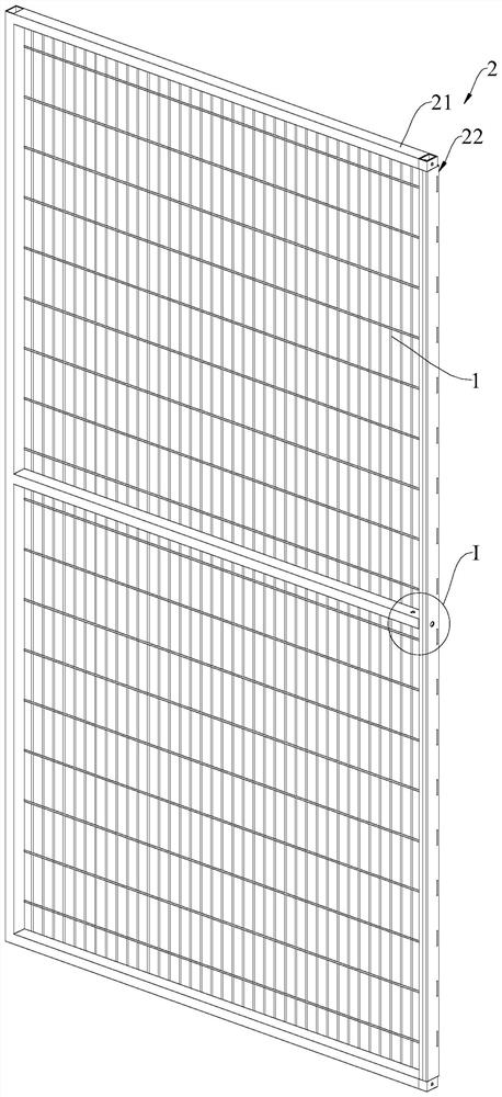
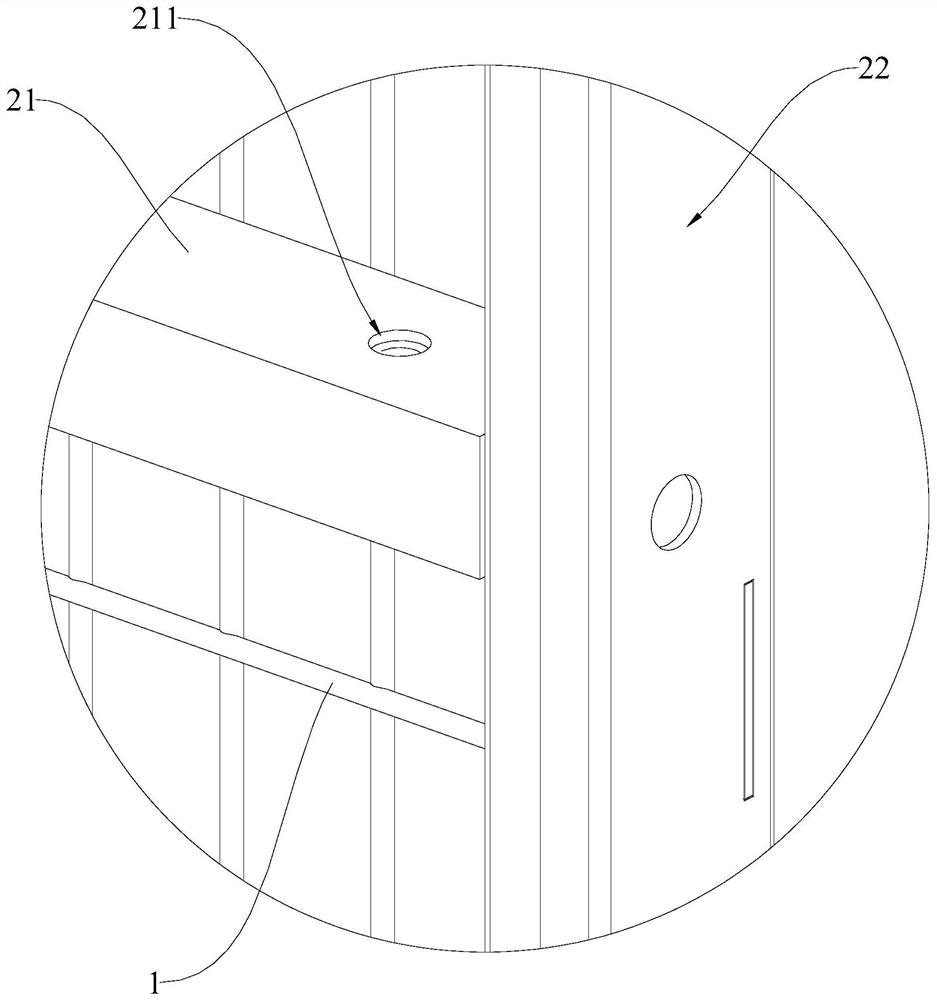
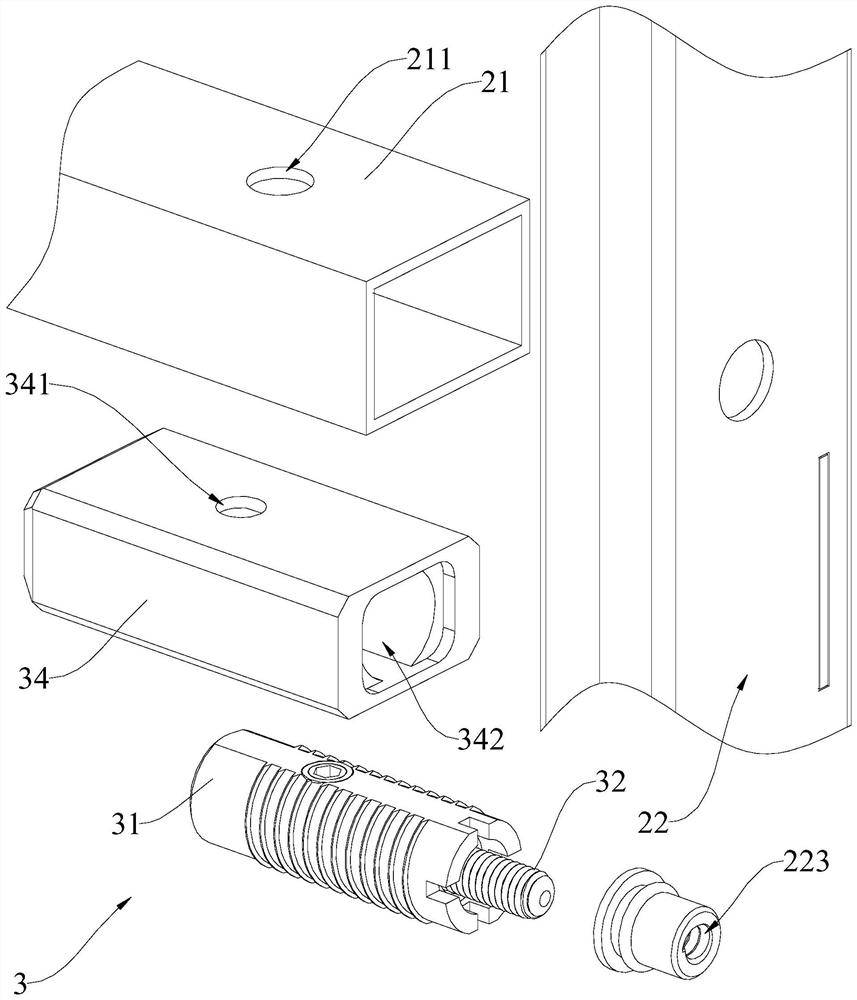
The invention discloses a fence mesh plate and a fence system with the fence mesh plate. The fence mesh plate comprises a mesh surface body, a safe edge body and a connecting piece; the safe edge body comprises an original safe edge and an added safe edge, and the side face of the added safe edge is provided with a threaded hole and a protection part. The connecting piece comprises a shell, a connecting rod and a driving assembly; one end of the shell is provided with an opening, the side surface of the shell is provided with a mounting hole, and the shell is arranged inside the original safe edge; one end of the connecting rod is rotatably and axially slidably connected into the shell, and the other end of the connecting rod is provided with external threads; the driving assembly is arranged in the mounting hole and used for driving the connecting rod to rotate. The fence system comprises a plurality of stand column bodies, and a fence net plate is arranged between every two adjacent stand column bodies. The fence mesh plate and the fence system are high in universality, convenient to mount, high in mounting efficiency, low in working intensity and high in safety, and attractiveness is not affected.

Description


Claims


Application Information

Patent Timeline
Owner VICHNET COMM SCI & TECH
Why Eureka
Try Eureka