Distributed radar target detection method and device based on dynamic multi-scale grids

A radar target, multi-scale technology, applied in measurement devices, radio wave measurement systems, radio wave reflection/re-radiation, etc., can solve the problem that grid and index relationships occupy a lot of memory resources, and it is difficult to meet the development needs of high-efficiency detection , low detection efficiency, etc., to reduce the detection range, reduce the occupation of memory resources, and ensure the detection accuracy.

Active Publication Date: 2022-07-29
INFORMATION SCI RES INST OF CETC
View PDF6 Cites 0 Cited by
  • Summary
  • Abstract
  • Description
  • Claims
  • Application Information

AI Technical Summary

Benefits of technology

This technology uses multiple sensors arranged along an axis called a cube or rectangular lattice (a type of geometric shape) to create 3D scans on objects within their environment. By measuring these points at different angles around it, we can determine how far away they are located based upon factors like radio wave speed and direction. These measurements help us improve our ability to detect targets accurately while reducing resource usage compared to traditional methods such as Liquid Crystal Display Displays (LCD).

Problems solved by technology

This patented technical problem addressed by this patents relates to how efficient and accurate detecting can be achieved for various types of targets such as vehicles or people moving around within complicated electric environment with many sensors located at different locations.

Method used


Image

  • Distributed radar target detection method and device based on dynamic multi-scale grids
  • Distributed radar target detection method and device based on dynamic multi-scale grids
  • Distributed radar target detection method and device based on dynamic multi-scale grids

Examples


Embodiment Construction

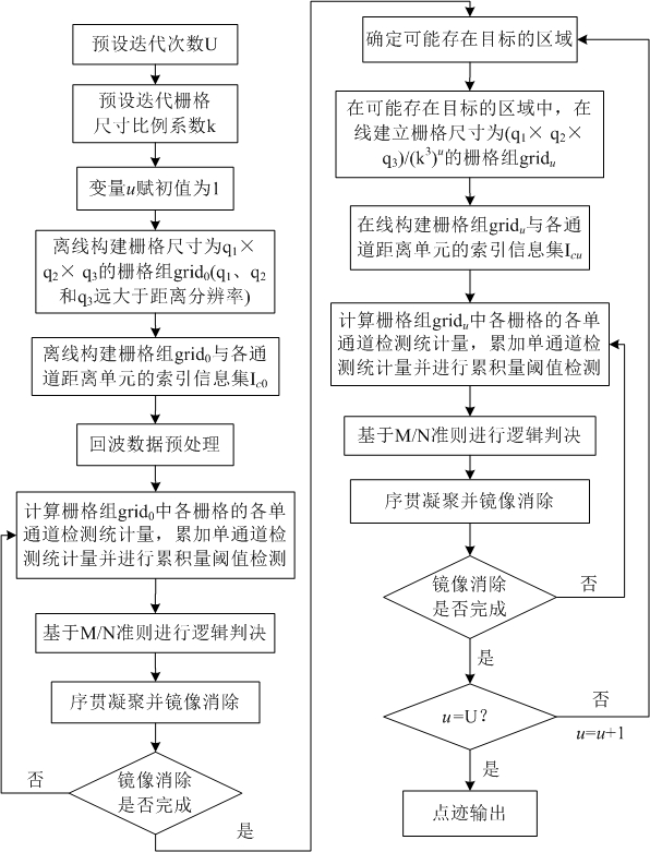
[0065] In the prior art, a collaborative detection system detection method based on spatial grid division includes the following steps:

[0066] Step S1: Build a three-dimensional space grid 3d , the three-dimensional detection space is evenly divided into rectangular grids whose longitude, latitude, and height are △Lo, △La, and △H, respectively.

[0067] Step S2: Calculate the azimuth angle corresponding to each three-dimensional grid and each radar node θ ,Pitch angle and distance R .

[0068] Step S3: Preprocessing the echo data of each channel, that is, performing matched filtering processing and moving target detection processing on the echo data of each channel, and outputting a sequence of preprocessing results: ,in, Y c ( l ) means the first c channel l A sequence of preprocessing results of distance units, m is the pulse number, and Mp is the number of pulses. y c [ l , m ] is the first c channel l the first distance unit m A sequence of preprocessing


PUM


Abstract

The invention relates to the field of radar target detection, and provides a distributed radar target detection method and device based on a dynamic multi-scale grid. The method comprises the following steps: firstly, dividing a three-dimensional detection space by using a cuboid grid of which the size is far greater than the radar distance resolution, establishing an index between a large-size grid and each channel echo signal distance unit, and traversing a grid region to complete first target detection; and then iterative detection is carried out, that is, the detection range is continuously reduced according to the position of the existing target and the neighborhood range thereof obtained by last target detection, grids with smaller sizes are divided in real time in the reduced detection range, indexes of the grids with the smaller sizes and echo signal distance units of all channels are established, grid detection is carried out, and the detection accuracy is improved. According to the invention, the detection precision is ensured, the detection efficiency is effectively improved, the dynamic construction of the grid region and the index relationship is realized, and the occupation of the storage grid and the index relationship on memory resources is effectively reduced.

Description


Claims


Application Information

Patent Timeline
Owner INFORMATION SCI RES INST OF CETC
Why Eureka
Try Eureka