Multi-stage brake power assisting device of new energy automobile
A technology for new energy vehicles and power assist devices, applied in electric vehicles, brake transmission devices, power management and other directions, can solve hidden dangers, vacuum power brake system failure safety, shorten the service life of motors and other problems, achieve rapid heat dissipation, reduce accidents Probability of accidents, effect of avoiding excessive friction
- Summary
- Abstract
- Description
- Claims
- Application Information
AI Technical Summary
Benefits of technology
Problems solved by technology
Method used
Image

Examples
Embodiment 1
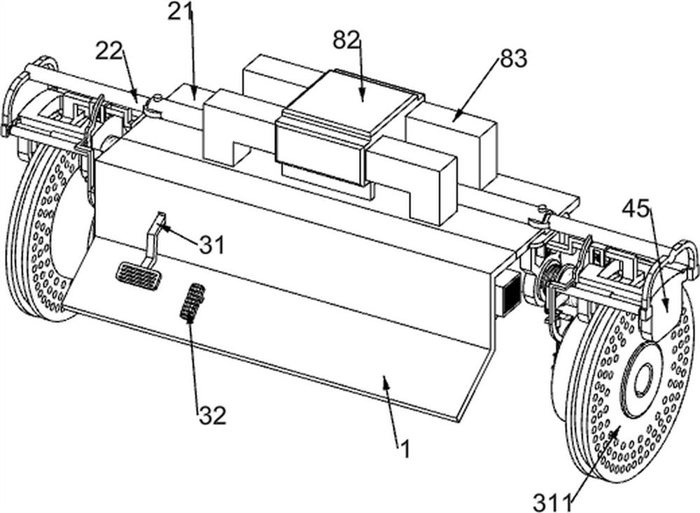
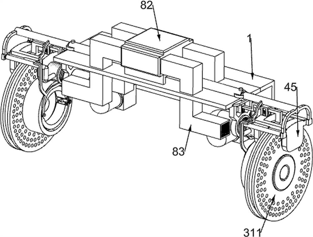
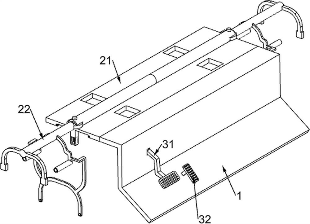
[0042] New energy vehicle multi-level brake booster, such as figure 1 , figure 2 , image 3 , Figure 4 , Figure 5 , Image 6 , Figure 7 , Figure 8 , Figure 9 , Figure 10 , Figure 11 , Figure 14 , Figure 15 , Figure 16 , Figure 17 , Figure 18 and Figure 19 As shown, it includes a baffle 1, a rectangular support plate 21, a special-shaped support frame 22, a brake pedal 31, an accelerator pedal 32, a rectangular slotted frame 33, a pressing rack frame 34, a first return spring 35, and a transmission gear 36 , missing gear 37, slotted shaft 38, 7-shaped slotted frame 39, second return spring 310, point brake assembly 4 and short brake assembly 5, the rear side of the baffle 1 is fixedly installed with a rectangular support plate 21, so The rectangular support plate 21 is fixedly mounted with a special-shaped support frame 22, the front left side of the baffle 1 is rotatably connected with a brake pedal 31 for controlling the brake of the automobile, and
Embodiment 2
[0048] On the basis of Example 1, as Figure 12 As shown, it also includes a long brake assembly 6, the special-shaped support frame 22 is provided with a long brake assembly 6, the long brake assembly 6 is used to brake the car for a long time, and the long brake assembly 6 includes a hydraulic pipe Three 61, the sliding rack 62, the slotted support block 63, the first return spring 64, the camshaft 65, the adjusting gear 66, the countersunk shaft 67, the shoe-shaped brake pad 68 and the first torsion spring 69, the special-shaped The support frame 22 is fixedly connected with two hydraulic pipes 61 for conveying hydraulic oil. The hydraulic pipe 3 61 on the same side is slidably connected with the hydraulic pipe 1 52, and the hydraulic pipe 61 is slidably connected with sliding teeth. The rack 62, the front part of the special-shaped support frame 22 is symmetrically provided with a slotted support block 63, the slotted support block 63 is slidably connected with the sliding ra
Embodiment 3
[0051] On the basis of Example 2, as Figure 13 , Figure 14 and Figure 15 As shown, it also includes an emergency brake assembly 7, the baffle 1 is provided with an emergency brake assembly 7, the emergency brake assembly 7 is used to brake the car during emergency braking, and the emergency brake assembly 7 includes a sliding Block 71, second return spring 72, rectangular slide rail frame 73, pressing rack 2 74, hole gear 75, compression spring 761, lower pressure rod 76, first return spring 77, L-shaped brake pad 771 and the second restoring spring 78, the slotted shaft 38 is slidably connected with a sliding block 71 in a circumferentially distributed manner, and a second return spring 72 is connected between the sliding block 71 and the slotted shaft 38, A rectangular slide rail frame 73 is fixedly installed on the right side of the inner top of the baffle plate 1 , and a second pressing rack frame 74 is slidably connected to the rectangular slide rail frame 73 . A compres
PUM
 Abstract
Description
Claims
Application Information
 - R&D Engineer
- R&D Manager
- IP Professional
- Industry Leading Data Capabilities
- Powerful AI technology
- Patent DNA Extraction
Browse by: Latest US Patents, China's latest patents, Technical Efficacy Thesaurus, Application Domain, Technology Topic.
© 2024 PatSnap. All rights reserved.Legal|Privacy policy|Modern Slavery Act Transparency Statement|Sitemap