System, method and device for measuring floors based on IMU (Inertial Measurement Unit) and photoelectric sensor, and medium

A photoelectric sensor and floor technology, applied in the field of robotics, can solve the problems of space limitation, poor operability, increasing the complexity of deployment personnel, and unreliability of program operation, and achieves the effect of overcoming space limitations and strong adaptability.

Pending Publication Date: 2022-08-02
上海景吾酷租科技发展有限公司
View PDF1 Cites 0 Cited by
  • Summary
  • Abstract
  • Description
  • Claims
  • Application Information

AI Technical Summary

Benefits of technology

This patented technology helps ensure accurate measurements for an elevators system during operation even when there are no physical connections between them or they may have issues related thereto. It also allows for easier adjustment based upon factors like weight distribution, shaft length, etc., which makes it possible to improve performance while minimizing costs associated with installing new equipment.

Problems solved by technology

Technological Problem addressed in this patented describes how robotic devices like escalators or lift gates interact safely during their movement across multiple levels within buildings without requiring any communications between them (such as wired connections). Current methods involve manually collecting measurements from each device's location, making sure they don’t interfere too much with other equipment located nearby. However, these techniques may result in errors due to factors like human error or environmental issues affecting signal reception. Additionally, some solutions rely heavily upon machine learning models trained over large amounts of data collected from different locations around the building. These systems often suffer from complexities and lack reliance on physical contact, limiting usable scenarios where the elevating platform could move freely.

Method used


Image

  • System, method and device for measuring floors based on IMU (Inertial Measurement Unit) and photoelectric sensor, and medium

Examples


Embodiment Construction

[0032] The present invention will be described in detail below with reference to specific embodiments. The following examples will help those skilled in the art to further understand the present invention, but do not limit the present invention in any form. It should be noted that, for those skilled in the art, several changes and improvements can be made without departing from the inventive concept. These all belong to the protection scope of the present invention.

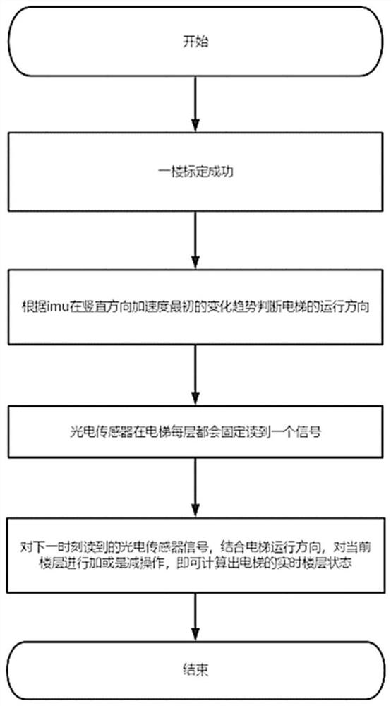
[0033] like figure 1 As shown, the present invention provides a system for measuring floors based on IMU and photoelectric sensors, including:

[0034] Module M1: regularly read the data of the IMU deployed in the elevator to obtain the acceleration of the elevator in the vertical direction.

[0035] Module M2: Judging the running direction of the elevator according to the initial change trend of the IMU acceleration in the vertical direction, the module M2 uses the acceleration of gravity as the benchmark, and t


PUM


Abstract

The invention provides a system for measuring floors based on an IMU (Inertial Measurement Unit) and a photoelectric sensor, which comprises a module M1 for regularly reading data of the IMU deployed in an elevator so as to obtain the acceleration of the elevator in the vertical direction; the module M2 is used for judging the running direction of the elevator according to the initial change trend of the acceleration of the IMU in the vertical direction; the module M3 is used for fixedly reading a signal value on each floor of the elevator through a photoelectric sensor; the module M4 is used for carrying out addition or subtraction operation on the current floor by combining the signal value read by the photoelectric sensor with the running direction of the elevator, so that the real-time floor state of the elevator can be calculated; wherein the initial floors of the elevator are all calibrated on the first floor. The basic operation state of the elevator can be obtained without a butt joint protocol with an elevator manufacturer; and by adopting the IMU and the photoelectric sensor to measure the floor, the adaptability is higher, and the limitation of space is avoided.

Description


Claims


Application Information

Patent Timeline
Owner 上海景吾酷租科技发展有限公司
Why Eureka
Try Eureka