Method and appts. for remote control transmission

A technology of remote control and signal, applied in the field of remote control transmission

Inactive Publication Date: 2006-03-29
THOMSON LICENSING SA
View PDF0 Cites 0 Cited by
  • Summary
  • Abstract
  • Description
  • Claims
  • Application Information

AI Technical Summary

Problems solved by technology

However, it has been determined that providing a pulse of only ten microseconds betwe

Method used


Image

  • Method and appts. for remote control transmission
  • Method and appts. for remote control transmission
  • Method and appts. for remote control transmission

Examples


Embodiment Construction

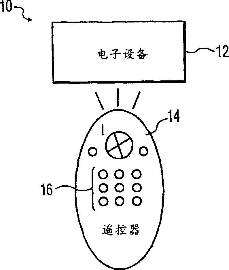
[0027] Now, referring to the accompanying drawings, more specifically figure 1 , shows an exemplary electronic system, generally designated 10, in which the present invention is embodied. Electronic system 10 includes electronic device 12 and remote control 14 . Electronic device 12 represents any type of electronic device, and more specifically, any type of consumer electronic device. The consumer electronic device may be a TV, a TV signal receiving device, a video recorder (VCR), a digital versatile disc player (DVD) and the like. Remote control 14 represents a typical, handheld remote control capable of generating and sending a control signal that transmits or represents an action performed by electronic device 12 in response to actuation of buttons or keys 16 of remote control 14 .

[0028] Transmission of the remote control signal is preferably accomplished wirelessly and may take any form such as via radio frequency signals, infrared (IR) radiation or the like. The remot


PUM


Abstract

A remote control is operative to transmit a remote control signal composed of a first portion and a second portion. The first and second portions are typically a pulse and a space. The pulse has a pulse width of a given duration within a pulse width range, while the space has a space width of a given duration within a space width range. An interrupt signal provided to indicate the end of transmission of the remote control signal is disabled when a space portion requires a space width greater than the space width range. The interrupt signal signaling the end of the remote control transmission is then disabled for a predetermined period of time essentially equivalent to a length of time that the additional space exceeds the space width. During the predetermined period of time, the remote control thus transmits a space. The interrupt signal is then re-enabled after expiration of the predetermined period of time in order to allow for another remote control transmission.

Description


Claims


Application Information

Patent Timeline
Owner THOMSON LICENSING SA
Why Eureka
Try Eureka