Damping extent variable optical fiber collimator using micromechanism
A fiber collimator and micro-mechanical technology, applied in optics, instruments, nonlinear optics, etc., can solve the problem of not having variable attenuation, and achieve the effect of low cost, easy integration and replacement
- Summary
- Abstract
- Description
- Claims
- Application Information
AI Technical Summary
Problems solved by technology
Method used
Image

Examples
Embodiment 1
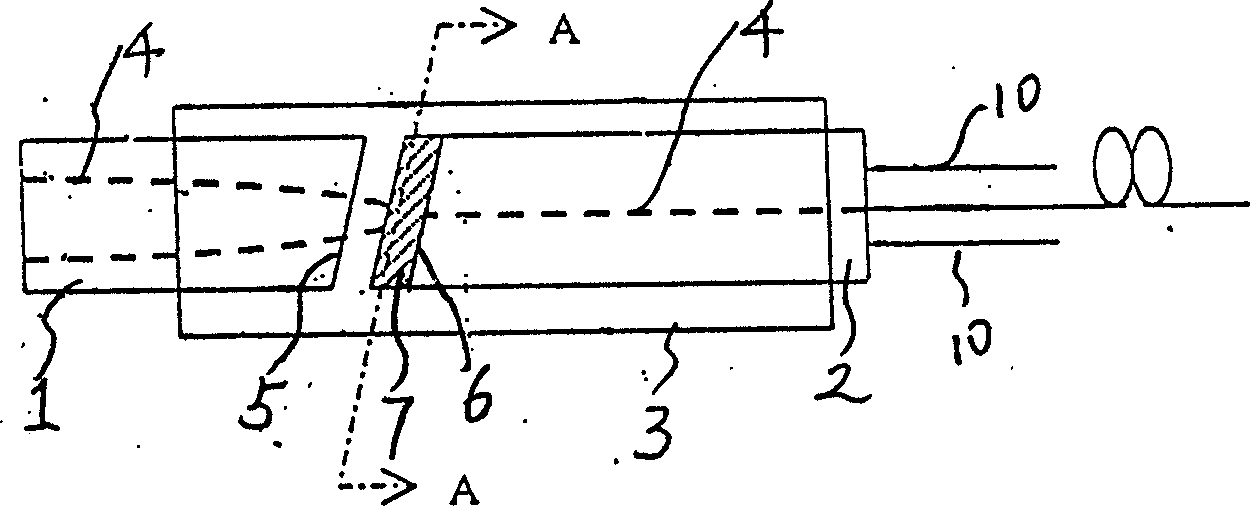
[0027] Embodiment 1: lens 1 (using refractive index lens or ball lens) and pigtail 2 (using single fiber or double fiber, triple fiber) are fixed together by precision fixing tube 3, and there is space between lens 1 and pigtail 2 hole. At the right end of the pigtail 2 is a group of optical fibers (can be a single fiber or any possible number of multi-fibers). The light incident from the left end of the lens 1 enters the light entrance at the left end of the pigtail 2 after being focused, and the light is guided out by the optical fiber. Or the light incident from the right end of the optical fiber is emitted from the left end of the pigtail, collimated by the lens 1 and emitted from the left end. The reversible optical path 4 shows the transmission path of light in the lens 1 and the pigtail 2 . In order to achieve good return loss, it is common to make the set of faces 5, 6 where the lens and pigtails cooperate form an appropriate angle (eg 8 degrees) to the axis.
[0028]
Embodiment 2
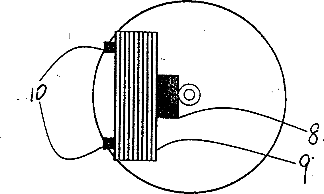
[0030] Embodiment 2: The micromechanical attenuation control device 11 is installed on the inclined plane 14 of the cavity between the lens 12 and the pigtail 13, and has a light barrier 16 connected to the elastic conductive cantilever 15, the light barrier 16 is just positioned on the right side of the light port in the plane, and a conductive force applicator 17 is fixed on the left side of the light port. The attractive force between the force applicator 17 and the light barrier 16 can be controlled by the electrode 18, so that the light barrier 16 protrudes into or withdraws from the light beam. The function of the light barrier 16 is to make the light overlapping with it deviate from the original light path or be absorbed.
[0031] When no voltage is applied between the electrodes, the light barrier 16 does not overlap with the light beam, and the fiber collimator has no additional loss. When a voltage is applied between the electrodes, charges are rapidly accumulated on t
Embodiment 3
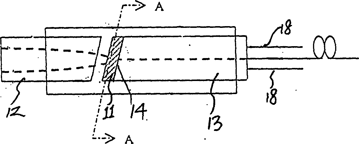
[0032] Embodiment 3: The micromechanical attenuation control device includes a double metal wire light barrier 19 installed on the pigtail plane, and the double metal wire light barrier 19 is connected to the electrode 20 . The dual wire shutter 19 can be heated by supplying an electric current through the electrodes so that the shutter 19 enters or exits the beam. The effect of light barrier 19 is to make the light overlapping with it deviate from the original light path and be absorbed.
[0033] When no current is applied between the electrodes 20, the light barrier 19 does not overlap with the light beam, and the fiber collimator has no additional loss. When the current is applied between the electrodes, the bimetal of the light barrier quickly accumulates heat and raises the temperature. Due to the difference in the expansion coefficient of the two materials, the bimetallic wire bends, and the light barrier enters the optical path, so that the transmitted light energy is atte
PUM
 Abstract
Description
Claims
Application Information
 - R&D Engineer
- R&D Manager
- IP Professional
- Industry Leading Data Capabilities
- Powerful AI technology
- Patent DNA Extraction
Browse by: Latest US Patents, China's latest patents, Technical Efficacy Thesaurus, Application Domain, Technology Topic.
© 2024 PatSnap. All rights reserved.Legal|Privacy policy|Modern Slavery Act Transparency Statement|Sitemap