Methods for treating deodorizer distillate
A technology of fraction and concentration zone, applied in the field of processing deodorant fraction, can solve the problems of time-consuming, residual solvent pollution, expensive processing steps, etc.
- Summary
- Abstract
- Description
- Claims
- Application Information
AI Technical Summary
Problems solved by technology
Method used
Image

Examples
Embodiment 1
[0043] The evaporated fraction at about 300°F from the deodorization of organically extracted soybean oil flows at a flow rate of 250,000 lbs. Operate under pressure. The deodorant fraction contains about 50% by weight fatty acids, about 12% by weight tocopherols, about 14% by weight sterols, and about 24% by weight other components including oils.
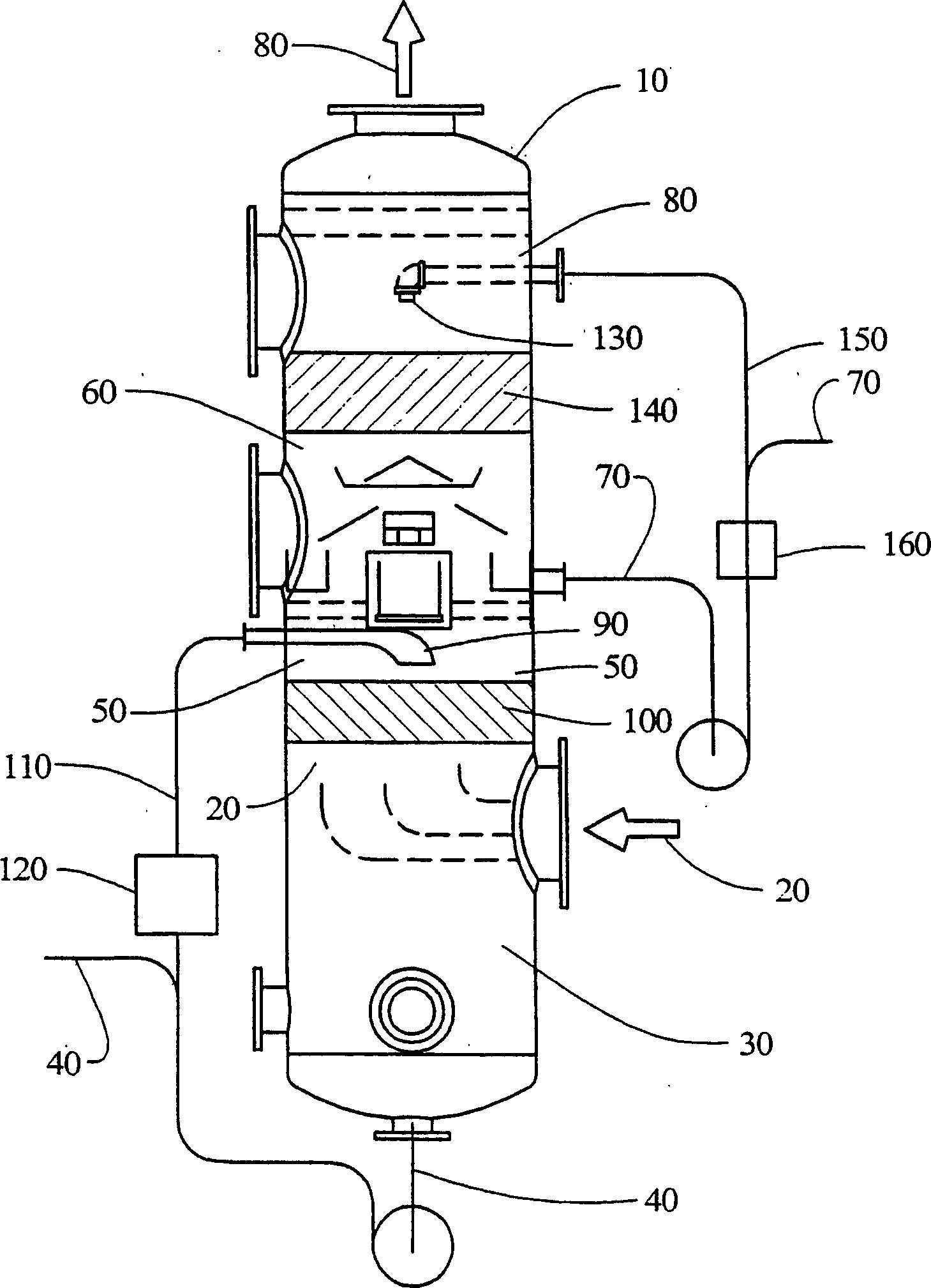
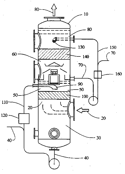
[0044] The scrubbers consisted of cylindrical columns 14 feet high and 42 inches in diameter. The first enrichment zone is about 4 feet high and includes a fill zone with a vertical dimension of 15 inches. The packing zone within the first concentration zone contains a plurality of closely spaced serrated stainless steel discs provided with a plurality of holes. The nozzles extend into the first concentration zone above the fill zone. Vacuum is provided to the scrubber by Nash-kinema three-stage vacuum system or vacuum pump.
[0045] A first portion containing about 50 wt% of the evaporated fraction entering the first concentrati
Embodiment 2
[0054] The evaporated fraction at a temperature of about 330°F from the deodorization of conventionally refined soybean oil flows into the first enrichment zone of a scrubber at a flow rate of 250,000 lbs. Operate under the pressure of Hg. The deodorant fraction contains about 45% by weight fatty acids, about 15% by weight tocopherols, about 20% by weight sterols, and about 20% by weight other components including oils.
[0055] The scrubber consists of a cylindrical tower 18 feet high and 60 inches in diameter. The first enrichment zone is about 5 feet high and includes a fill zone with a vertical dimension of 24 inches. The packing zone in the first concentration zone contains a plurality of closely spaced serrated stainless steel discs with a plurality of holes. The nozzles extend into the first concentration zone above the fill zone. Vacuum is provided to the scrubber by Nash-kinema three-stage vacuum system or vacuum pump.
[0056] The first portion containing about 55 w
PUM
 Abstract
Description
Claims
Application Information
 - R&D Engineer
- R&D Manager
- IP Professional
- Industry Leading Data Capabilities
- Powerful AI technology
- Patent DNA Extraction
Browse by: Latest US Patents, China's latest patents, Technical Efficacy Thesaurus, Application Domain, Technology Topic.
© 2024 PatSnap. All rights reserved.Legal|Privacy policy|Modern Slavery Act Transparency Statement|Sitemap