CT assisted bone imitated producing artificial bone method

An artificial bone and bone imitation technology, which is used in bone implants, 3D image processing, medical science and other directions, can solve the problems of large errors in fitting, difficult to achieve accuracy, and low artificial bone accuracy, and achieve fast speed. , reduce human-computer interaction, the effect of fast measurement

Inactive Publication Date: 2005-01-12
TSINGHUA UNIV
View PDF0 Cites 8 Cited by
  • Summary
  • Abstract
  • Description
  • Claims
  • Application Information

AI Technical Summary

Problems solved by technology

[0003] The main disadvantages of this method are: first, the measurement cannot measure the internal structure of the bone; second, it is very difficult to manually measure the complex surface of the bone to obtain enough data sets; third, it is very difficult to fit the measured discrete data of the imitation bone Creating a vector CAD model requires a lot of human-computer interaction work, and the fitting has a large error. This method is limited to only designing the shape of the skeleton, and the internal geometric shape is often impossible to measure. It is difficult to establish a model that meets the physical measurement The accuracy of the artificial bone is not high, resulting in low precision of the artificial bone

Method used


Image

  • CT assisted bone imitated producing artificial bone method
  • CT assisted bone imitated producing artificial bone method
  • CT assisted bone imitated producing artificial bone method

Examples


Example Embodiment

[0014] The CT-assisted bone-like artificial bone manufacturing method proposed by the present invention is described in detail as follows with reference to the drawings and embodiments:

[0015] This embodiment includes the following steps:

[0016] Step 1: Take a long bone of a cow as a bone prototype, and use micro-focus or small-focus X-CT to obtain CT tomographic images of the bone, such as figure 1 Shown is a CT tomographic image of a bone. The bone in the picture is a structure with a complex shape, internal shape, and small holes. Three-dimensional CT is used for overall measurement.

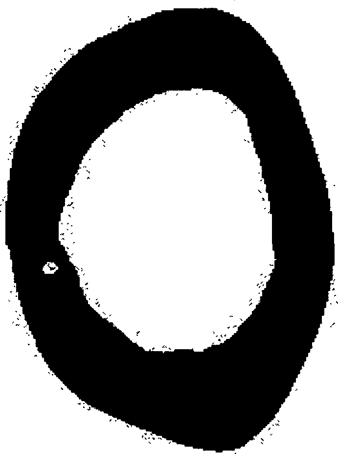
[0017] The second step: Binarize each CT tomographic image obtained in the first step with the best threshold method to obtain a new and clear image. The CT tomographic image after the binarization process is as follows figure 2 As shown, only black and white grayscales are retained. In the figure, the black indicates the position with the material, which should be filled with raw materials du


PUM


Abstract

A Ct aided bone copying method for preparing artificia bone includes scanning original bone by Ct machine to obtain the information about geometric profile of the bone, internal 3D porous structure and 3D density, quantizing the 3D information image to obtain a binary image, inputting ito a fast shaper, and making the artifial bone by stacking the 3D images.

Description


Claims


Application Information

Patent Timeline
Owner TSINGHUA UNIV
Why Eureka
Try Eureka