Electromagnetic valve drive circuit for engine

A solenoid valve driving and driving circuit technology, which is applied in engine control, machine/engine, electrical control, etc., can solve the problems of driving circuit driving ability, control accuracy, low duty cycle adjustment frequency, and complicated control software writing. , to achieve the effect of shortening the closing time, high precision of current control, and reducing the fluctuation range

Inactive Publication Date: 2005-01-12
TSINGHUA UNIV
View PDF0 Cites 28 Cited by
  • Summary
  • Abstract
  • Description
  • Claims
  • Application Information

AI Technical Summary

Problems solved by technology

In the high-end and low-end drive circuits, since the hardware circuit only provides the drive current feedback value, the control actions such as sampling and comparing the drive current and adjusting the duty cycle of the high-end power transistor control pulse must be completed by software. This control method is called It is called software current feedback control. The progr

Method used


Image

  • Electromagnetic valve drive circuit for engine
  • Electromagnetic valve drive circuit for engine
  • Electromagnetic valve drive circuit for engine

Examples


Embodiment Construction

[0014] The specific circuit and working process of the present invention will be described in detail below in conjunction with the embodiments and accompanying drawings.

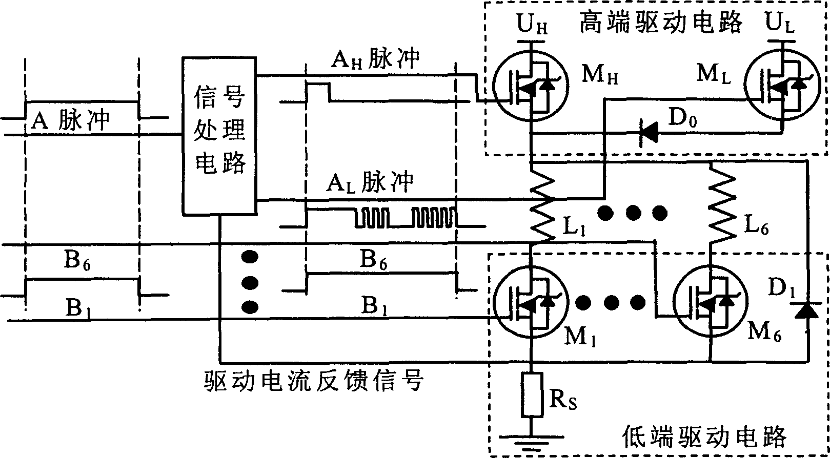
[0015] See figure 1 , the present invention mainly includes three parts: a high-end drive circuit, a low-end drive circuit and a signal processing circuit. Taking driving a six-way solenoid valve as an example, the high-end drive circuit is located in the solenoid valve L 1 -L 6 (L 2 -L 5 Not marked in the figure) one end, including two sets of independent drive power and power transistors, one set includes high-voltage drive power U H and high voltage power transistor M H (Model is IRFB61N15D), among them, the high-voltage driving power supply voltage is 100V±50V, generally 100V is desirable, and the high-voltage power transistor M H A output by the signal processing circuit H Pulse signal control. The other set includes low voltage drive power supply U L and low voltage power transistor M L (Model


PUM


Abstract

The circuit contains a single processing circuit, it receives the control pulse. A from the electronic control unit of the motor and output high voltage driving pulse Ah and low voltage driving pulse Al to higher extreme driving circuit separately and receive the feedback sampling current signal from lower extreme driving circuit, after processing, the low voltage driving pulse Al adjust the higher extreme driving circuit to adjust the driving circuit of the electromagnetic valve. Lower extreme driving circuit receive pulse signal B from electronic control unit of the motor, this pulse signal is same with the control signal A.

Description


Claims


Application Information

Patent Timeline
Owner TSINGHUA UNIV
Why Eureka
Try Eureka