Self cleaning type internal rotation flow membrane separating device
A technology of membrane separation and internal swirling flow, applied in the direction of filtration separation, separation method, swirling flow device, etc., can solve the problems of high operating cost, troublesome maintenance, separation membrane pollution, etc., and achieve simple and reasonable structural design, easy replacement or cleaning , Easy to install and disassemble
- Summary
- Abstract
- Description
- Claims
- Application Information
AI Technical Summary
Benefits of technology
Problems solved by technology
Method used
Image

Examples
Embodiment 1
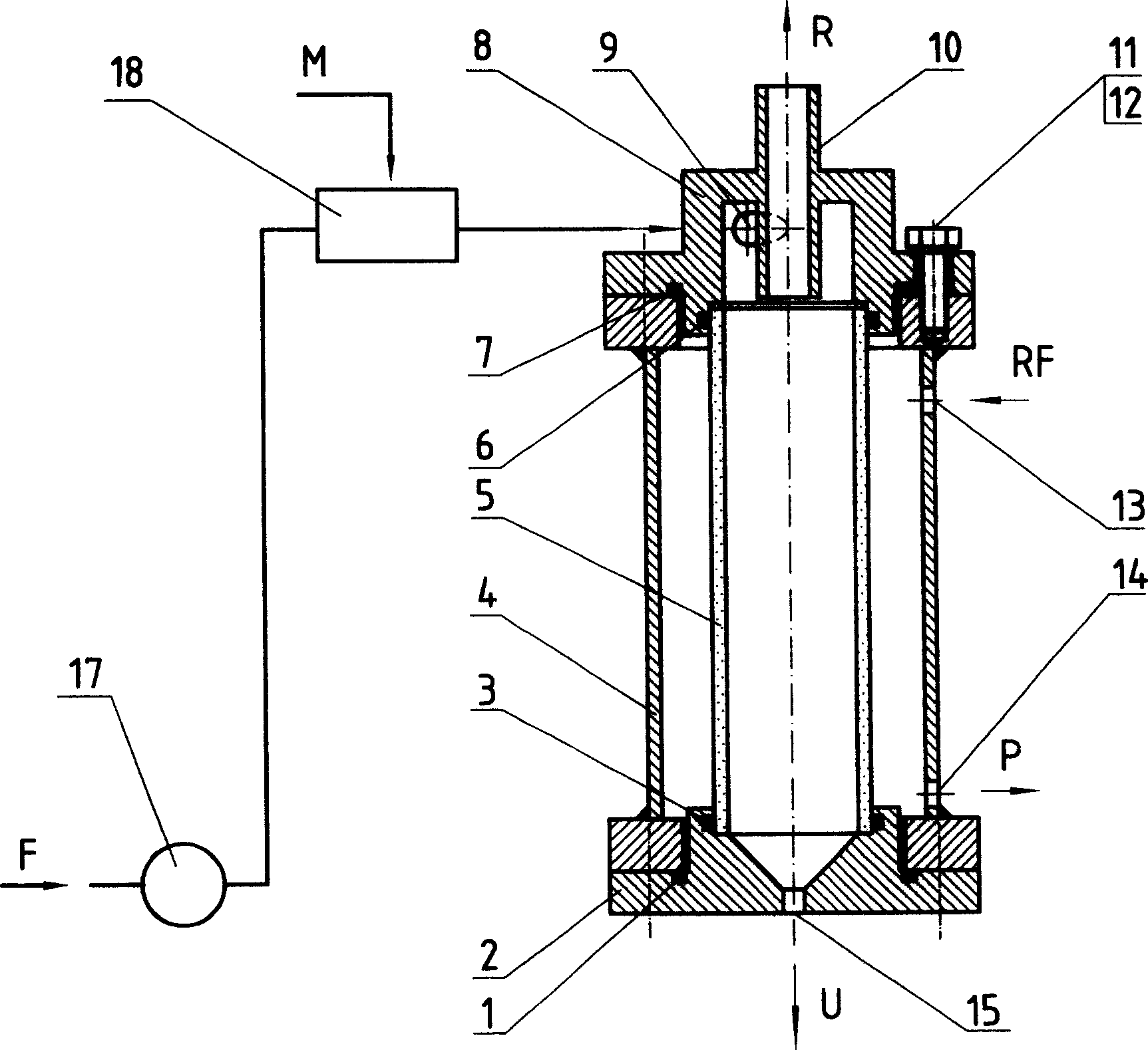
[0028] The structure of this embodiment is as attached figure 1 Shown is a membrane separation plant with a membrane separation unit tube in a pressure shell. In this embodiment, the membrane separation unit tube is composed of the membrane separation tube (5), the inlet part (8), the underflow port part (2) and the seals (1, 3, 6, 7), etc., with bolts (11) The inlet part (8) and the bottom flow port part (2) are assembled in a pressure casing (4) by welding or other methods, and the elastic ring washer (12) prevents the bolt (11) from loosening. The function of (1) and (7) is to prevent permeate or backflushing fluid from leaking out through the flange, while the function of seals (3) and (6) is to prevent the fluid in the membrane separation tube from leaking to the membrane separation tube ( 5) The space between the inner wall of the pressure shell (4) is mixed with the permeate. The shape of the pressure shell (4) is various, and the cylindrical pressure shell is preferred.
Embodiment 2
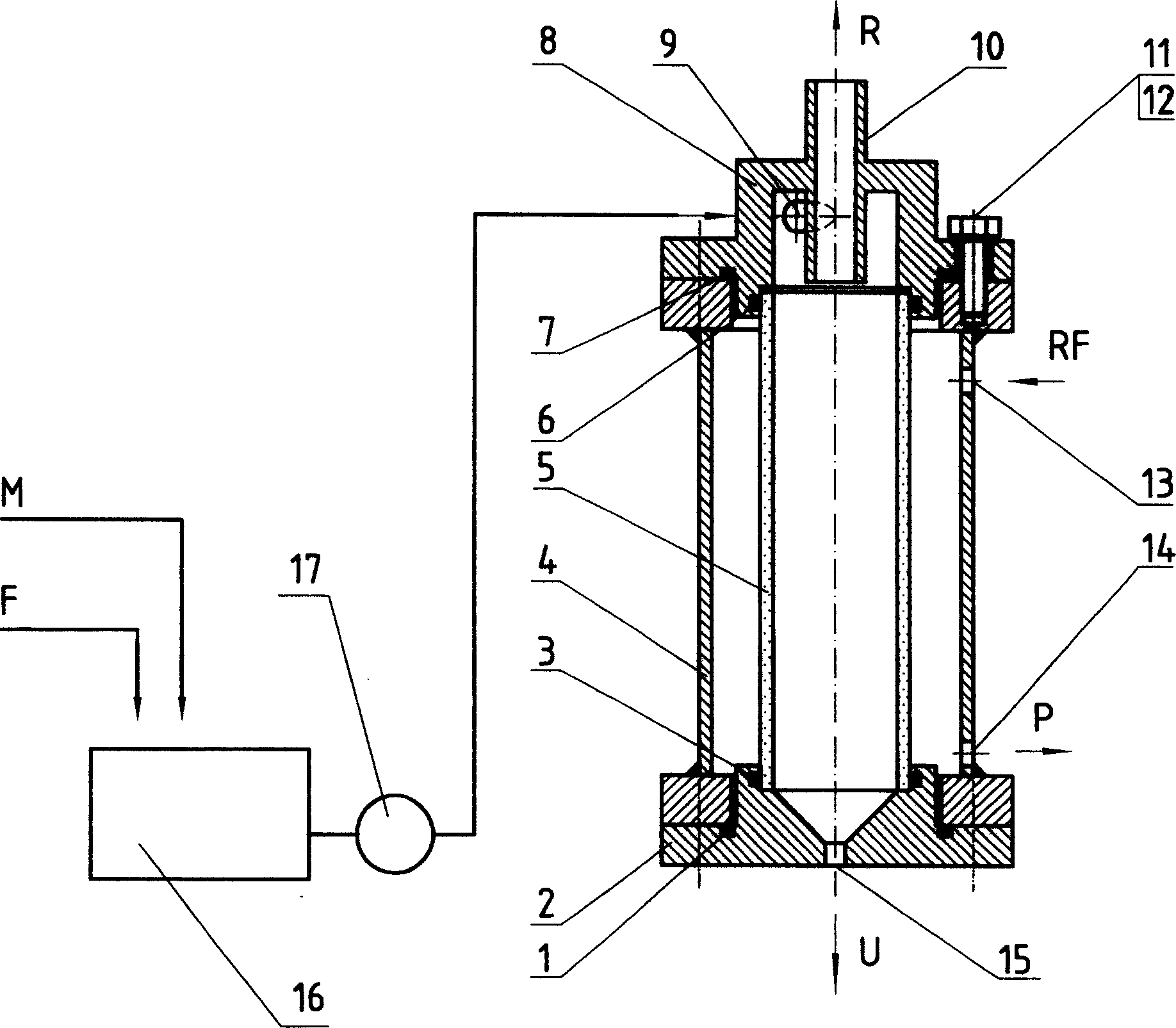
[0035] The structure of this embodiment is as attached figure 2 Shown is a membrane separation plant with a membrane separation unit tube in a pressure shell. In this embodiment, its main structure is exactly the same as that of Embodiment 1, except that the mixing of the self-cleaning material and the fluid to be separated is not carried out in the mixing device (18), but in a mixing tank (preferably a stirring tank) ( 16) is mixed first, and then transported to the inlet part (8) by the fluid transporting machine (17), thereby constituting the membrane separation device of the present invention.
Embodiment 3
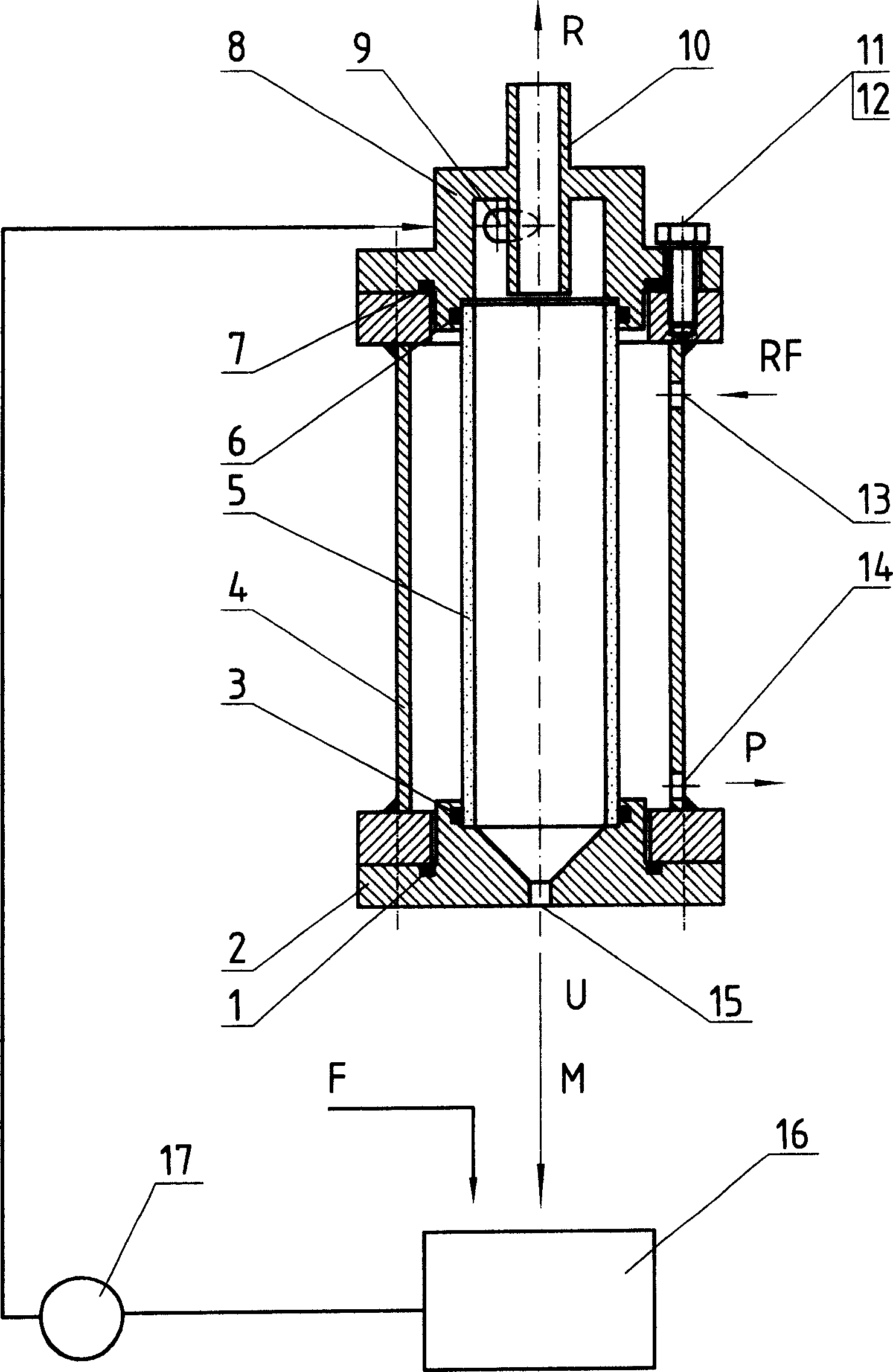
[0037] The structure of this embodiment is as attached image 3 Shown is a membrane separation plant with a membrane separation unit tube in a pressure shell. In this embodiment, its main structure is exactly the same as that of Embodiment 1, except that the self-cleaning material is added into the mixing tank (16) in advance, and the self-cleaning material is mixed with the fluid to be separated before being conveyed by the fluid conveying machine (17). It is conveyed to the inlet part (8), thereby constituting the membrane separation apparatus of the present invention. After the self-cleaning material is discharged from the underflow port (15) of the underflow port part (2), it directly enters the mixing tank (16) to be mixed with the fresh fluid to be separated. In this embodiment, the self-cleaning material can be recycled.
PUM
| Property | Measurement | Unit |
|---|---|---|
| The inside diameter of | aaaaa | aaaaa |
Abstract
Description
Claims
Application Information
 - R&D Engineer
- R&D Manager
- IP Professional
- Industry Leading Data Capabilities
- Powerful AI technology
- Patent DNA Extraction
Browse by: Latest US Patents, China's latest patents, Technical Efficacy Thesaurus, Application Domain, Technology Topic.
© 2024 PatSnap. All rights reserved.Legal|Privacy policy|Modern Slavery Act Transparency Statement|Sitemap