High-speed power-saving bicycle

A bicycle and high-speed technology, applied in the field of automatic shifting bicycles, can solve the problems of uneven pedaling force, excessive pedaling feeling, insufficient vehicle speed, etc., and achieve the effects of uniform effort, easy pedaling start, and vehicle speed improvement.

Inactive Publication Date: 2006-02-08
莫昌清
View PDF0 Cites 0 Cited by
  • Summary
  • Abstract
  • Description
  • Claims
  • Application Information

AI Technical Summary

Benefits of technology

This new technology improves how fast vehicles are driven by increasing their number of ratios between different parts of its drive system. It also makes it easier for people who want to use them harder because they don't have to manually operate these systems themselves. Additionally, this innovation allows cars that were previously only able to run at one specific speeds upward or downhill instead of being very smoothly going through all three levels of operation.

Problems solved by technology

The technical problem addressed for this patented technology relates to improving shiftable bike designs with better performance at lower or higher ratios while reducing power consumption compared to traditional methods like hydraulic systems.

Method used


Image

  • High-speed power-saving bicycle
  • High-speed power-saving bicycle
  • High-speed power-saving bicycle

Examples


Embodiment Construction

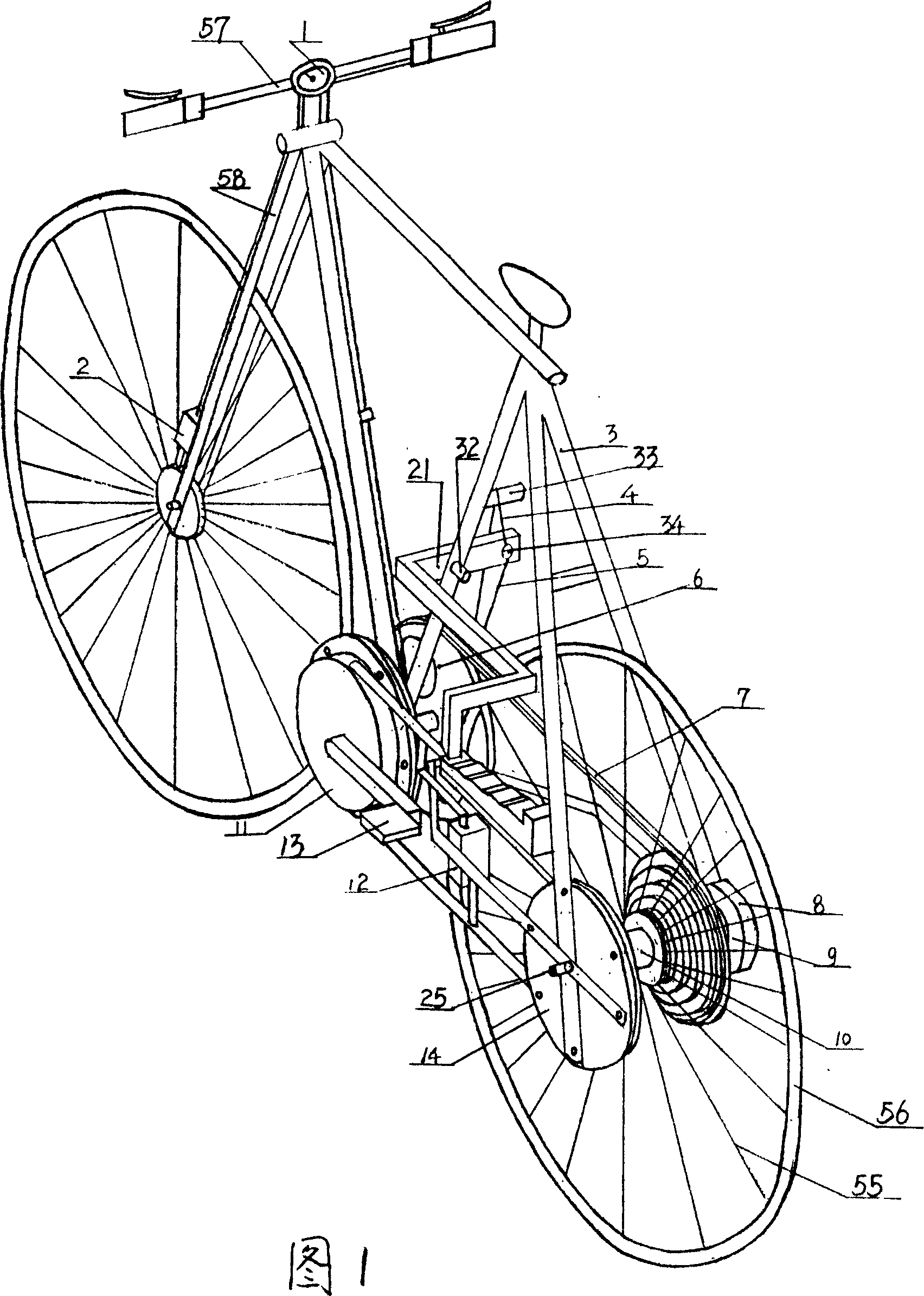
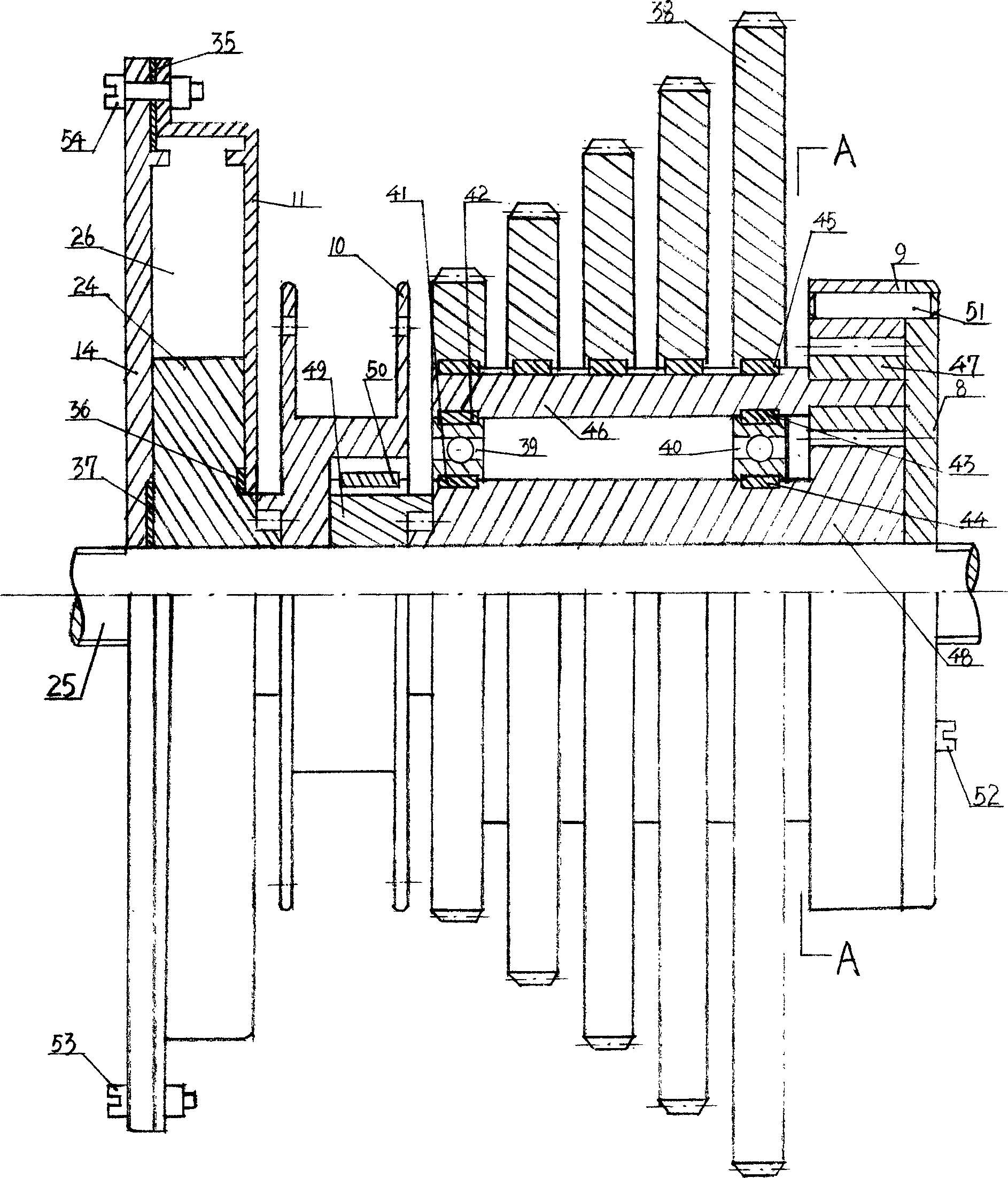
[0021] The present invention will be further described below in conjunction with accompanying drawing.

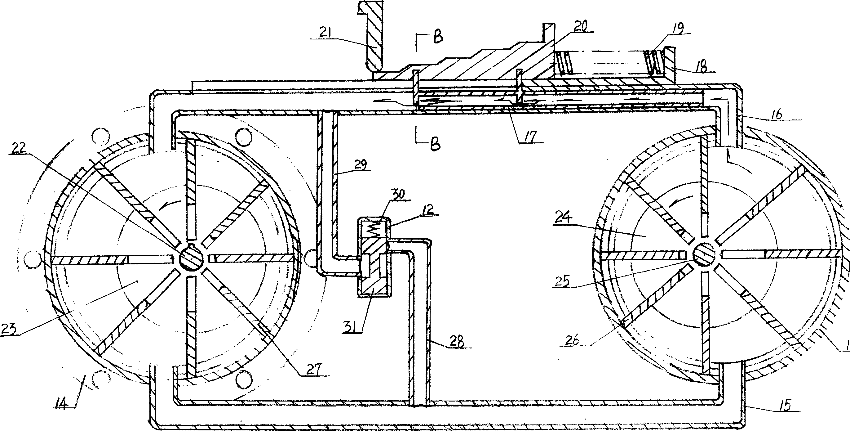
[0022] The invention is mainly divided into three parts: a planetary gear speed-up part, a hydraulic cycle labor-saving part, and a hydraulic automatic shifting part.

[0023] 1. Planetary gear speed-up structure and principle.

[0024] figure 1, figure 2 , Figure 4 Among them, the ring gear 9, the gear carrier 46, the pinion gear 47, and the sun gear 48 together form a planetary gear set. The sun gear 48 and the ratchet ring gear 49 are all sleeved on the rear wheel shaft 25, and can rotate relative to the rear wheel shaft 25. The rear wheel shaft 25 is fixed on the vehicle frame 3; On the gear frame 46; the bearings 39, 40 are respectively fixed on the gear frame 46 and the sun gear 48 through the keys 41, 42 and keys 43, 44; The inner ring gear 9 is fixed on the fixed plate 8 through the pin 51 and the screw 52, ​​and the fixed plate 8 is fixed with the vehicle frame 3


PUM


Abstract

The invention discloses a increasing speed but saving effort and automatic change speed high speed, labor saving bicycle. It comprises a handlebar, a frame, a pedal, a chain plate, a chain, a wheel and so on. The said rear axletree is equipped with a epicyclic gear group, the middle axle of the pedal and the rear axletree is equipped with a single-acting impeller pump separately, the two impeller pump connects with two pipes and forms a confinement hydraulic system, the handlebar is equipped with speedometer, the front wheel fork is equipped with a speed sensor. The invention can improve the speed of the current multi-speed bicycle a plurality of times, and the higher the speed is, the more labor is saved.

Description


Claims


Application Information

Patent Timeline
Owner 莫昌清
Why Eureka
Try Eureka