Light driving apparatus for liquid crystal display

A liquid crystal display and driving device technology, which is applied to lighting devices, static indicators, lamp circuit arrangements, etc., can solve the problem of not considering the frequency range of moving noise, and achieve the effect of stabilizing the PWM frequency and avoiding noise phenomena.

Inactive Publication Date: 2006-04-26
NANJING LG TONGCHUANG COLOR DISPLAYS SYST CO LTD
View PDF0 Cites 0 Cited by
  • Summary
  • Abstract
  • Description
  • Claims
  • Application Information

AI Technical Summary

Benefits of technology

The technology described allows for direct control over how much power each device uses during operation without being influenced from its surrounding temperatures or other factors like humidity levels. This makes sure that devices work properly even with different environmental conditions while maintaining their desired performance level. Additionally, this system automatically compensates for any variations caused by changing frequencies between 0%-100% of maximum efficiency at which they operate correctly.

Problems solved by technology

This patented technical describes different methods for controlling lamps called LED displays. These techniques involve varying the intensity level of each pixel's emitted light based upon its own characteristics. By doing this, these devices have improved image quality compared to traditional bulbs due to their lower energy consumption and longer life span. Additionally, they are able to reduce interference between adjacent pixels without affecting overall picture sharpness. Overall, these improvements improve performance and longevity of LED displays while reducing environmental impact caused by ambient factors such as heat fluctuations.

Method used


Image

  • Light driving apparatus for liquid crystal display
  • Light driving apparatus for liquid crystal display
  • Light driving apparatus for liquid crystal display

Examples


Embodiment Construction

[0028] Hereinafter, preferred embodiments of the present invention will be described in more detail with reference to the accompanying drawings.

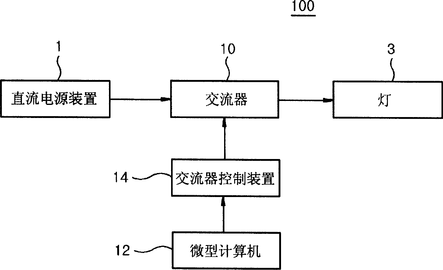
[0029] image 3 It is a schematic diagram of the structure of the LCD lamp driving device 100 according to an ideal embodiment of the present invention.

[0030] refer to image 3 , the lamp driving device 100 includes: a DC power supply device 1 that provides DC power; an AC converter 10 that converts the DC power input from the DC power supply device 1 into AC power and provides it to the power lamp 3; a microcomputer 12 that outputs PWM pulses of a certain frequency Receive the PWM pulse input from the microcomputer 12, regularly check the switching elements (for example, transistors) that the alternator 10 is equipped with, and convert the DC power provided by the DC power supply device 1 into the AC alternator control device 14.

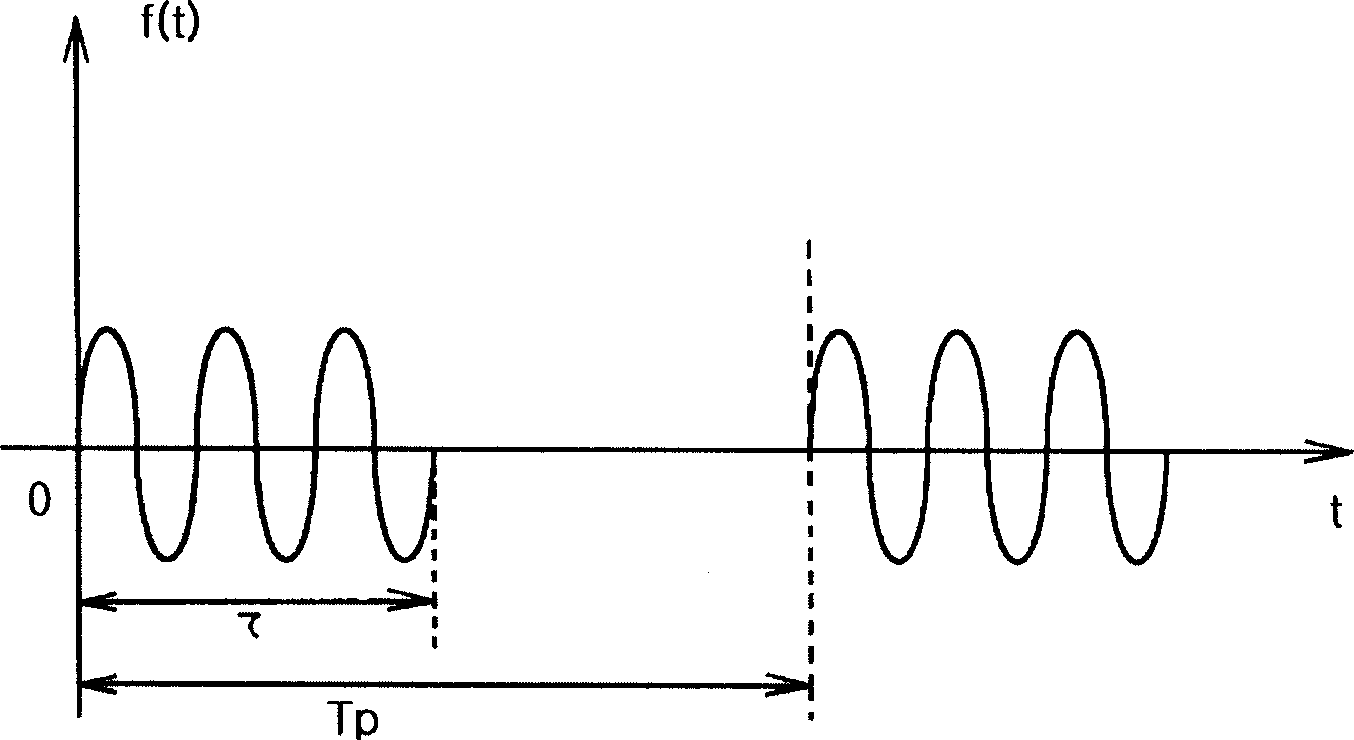
[0031] The PWM pulse according to the embodiment of the present invention is directly provided by t


PUM


Abstract

The invention discloses a LCD lamp driving device, which is characterized by the following: providing stable PWM frequency; transforming the PWM frequency into diversification numerical without environmental influence. The device contains direct current power device, alternating current unit, microcomputer, switch element and alternating current unit control device, wherein the alternating current unit transforms the direct current into the alternating current and provides the lamp; the microcomputer outputs a certain PWM impulse; the switch element receives the PWM impulse and examines the alternating current accessory periodically; the alternating current control device transforms the direct current into the alternating current.

Description


Claims


Application Information

Patent Timeline
Owner NANJING LG TONGCHUANG COLOR DISPLAYS SYST CO LTD
Why Eureka
Try Eureka