Telecom circuit protection apparatus

A technology of circuit protection and protection devices, which is applied in the direction of circuit devices, emergency protection circuit devices, emergency protection circuit devices for limiting overcurrent/overvoltage, etc., and can solve problems such as limiting fuse design parameters

Active Publication Date: 2006-07-12
贝尔保险丝公司
View PDF0 Cites 1 Cited by
  • Summary
  • Abstract
  • Description
  • Claims
  • Application Information

AI Technical Summary

Problems solved by technology

These conflicting requirements severely

Method used


Image

  • Telecom circuit protection apparatus
  • Telecom circuit protection apparatus
  • Telecom circuit protection apparatus

Examples


Embodiment Construction

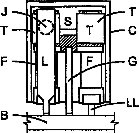
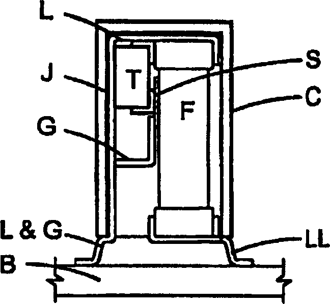
[0020] All electrical components release some heat when they are in use. When using fuses or PTCs, this heat is fatal to their proper function and is the focus of this invention. When enough current is passed through a fuse link or PTC, the internally generated heat can overcome losses from its connection end and its surface to its surroundings, and its element temperature can reach its melting / high impedance point, opening the fuse or Drives the PTC into its current-limit mode.

[0021] Semiconductor devices, such as thyristors, also release heat when they are turned on. The power dissipated is the product of the voltage drop across its front and the current through it. Most of the heat generated is dissipated through the solder joints of the device, with a small amount maintained on its surface. Unlike fuses, excessive temperature rise can impair the proper function of semiconductors. The temperature of the equipment joints must be maintained below its factory specified m


PUM


Abstract

A telecom circuit protection apparatus includes a housing having at least first and second temperature responsive circuit protection devices, such as a fuse and a thyristor disposed therein. A first metal lead is connected to respective first terminals of the first and second circuit protection devices and is structured and arranged such as to transfer heat freely between the second circuit protection device and the first circuit protection device. A second metal lead is connected to a second terminal of the first device and a third metal lead is connected to a second terminal of the second device. The first, second and third metal leads extend from the housing. Advantageously, the portions of the first, second and third metal leads extending from the housing have reduced cross-sections to reduce heat loss from the apparatus and are formed and made solderable for use as connection points for surface mount connection to the apparatus. To protect multiple service lines, a circuit protector is provided for each of them. In this case, the multiple circuit protectors may advantageously be collocated in a common housing having either a common or separate ground terminal(s).

Description


Claims


Application Information

Patent Timeline
Owner 贝尔保险丝公司
Why Eureka
Try Eureka