L-source inventer

A source inverter, three-phase inverter bridge technology, applied in the field of motor drive inverter, can solve the problems of upper and lower switching devices not allowed to be turned on at the same time, environmental pollution, affecting reliability, etc., to increase complexity, topology Simplified effect

Inactive Publication Date: 2006-10-25
NANJING UNIV OF AERONAUTICS & ASTRONAUTICS
View PDF0 Cites 8 Cited by
  • Summary
  • Abstract
  • Description
  • Claims
  • Application Information

AI Technical Summary

Problems solved by technology

Not suitable for occasions that need to increase the output voltage
[0004] (2) The voltage drop often interrupts the work of the power transmission system, which will make important loads and production processes work abnormally
Lack of overvoltage capability is a serious problem for sensitive loads
[0005] (3) The rectification and filtering circuit causes harmonic pollution to the power grid
[0006] (4) The upper and lower switching devices of each bridge arm are not allowed to be turned on at the same time, otherwise the device will be damaged; the direct connection caused by false triggering caused by electromagnetic interference is the main factor affecting its reliability
At the same time, there is still an obvious shortcoming in the utilization of traditional energy sources: causing environmental pollution
[0010] (1) Due to the addition of a Z-source network, which is a two-port network including inductance and capacitance, under certain conditions, the inductance and capacitor of the Z-source network will resonate. When designing and controlling the Z-source inverter, it must Consider strategies to avoid resonance, once resonance occurs, it will easily damage the circuit;
[0011] (2) The bus voltage is the capacitor voltage minus the inductor voltage drop. The bus voltage cannot make full use of the voltage level of the capacitor; The magnitude and direction of the current change and w

Method used


Image

  • L-source inventer
  • L-source inventer
  • L-source inventer

Examples


Example Embodiment

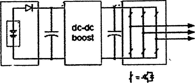
[0027] Embodiment 1: as Figure 5 As shown, the inverter of this embodiment is applied to a power supply that is a battery or other voltage source, and to make the DC bus voltage of the inverter much higher than the power supply voltage, it includes an inductor L connected to one end of the power supply, a positive The diode D connected between the end and the other end of the inductance L has a switching device T8 connected in parallel; the negative end of the diode D is connected with a three-phase inverter bridge, and the three-phase inverter bridge is composed of three parallel branches, and each branch includes Two switches, each of which is connected in parallel with a power tube, the negative end of one power tube is connected to the positive end of the other power tube, the positive end is connected to the other end of the power supply, and the negative end of the other power tube is connected to the The negative terminal of the diode D is connected; the three-phase inver

Example Embodiment

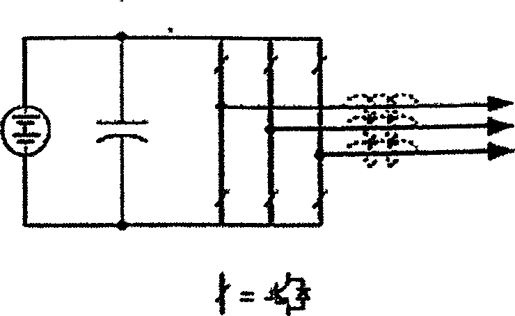
[0029] Embodiment 2: as Image 6 As shown, the inverter of this embodiment is applied to rectification occasions where the power supply is alternating current, or the occasions where the DC bus voltage of the inverter does not need to be greatly raised, then the diode D and the switching device T8 in Embodiment 1 are omitted can be achieved.


PUM


Abstract

This invention discloses a source L inverter including a three-phase inversion bridge and an inductor serial between the positive of a supply and a three-phase inversion bridge, which is parallel to a branch serial to a capacitor and a power switch device and the output end of the three-phase inversion bridge is connected with three phases of a motor necessary for being controlled and the inverter also includes a diode serial between the inductor and the bridge.

Description


Claims


Application Information

Patent Timeline
Owner NANJING UNIV OF AERONAUTICS & ASTRONAUTICS
Why Eureka
Try Eureka