Air purifying combustion-supporting device
An air purification and combustion booster technology, which is applied to machines/engines, engine components, mechanical equipment, etc., can solve the problem of insufficient activation, affecting the combustion effect and combustion efficiency and engine power, and the filter structure cannot purify oxygen and hydrogen quickly and effectively. and other problems to achieve the effect of increasing power and reducing pollution.
- Summary
- Abstract
- Description
- Claims
- Application Information
AI Technical Summary
Problems solved by technology
Method used
Image


Examples
Embodiment 1
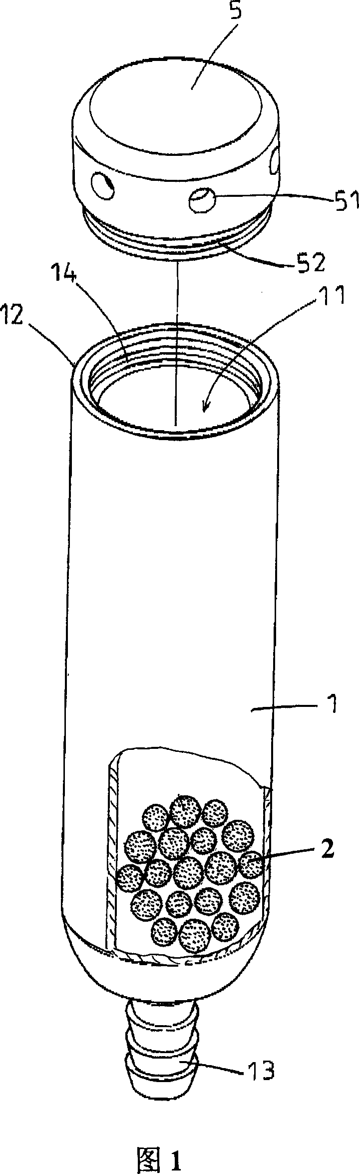
[0023] Please refer to Fig. 1, as the body 1 of the air purifying burner of the present invention is generally cylindrical, the center is the accommodation space 11, and one end, namely the upper end of the state shown in the figure, is formed with a The air inlet 12 in 11, the other end, that is, the lower end of the state shown in the figure, narrowly extends a gas outlet pipe 13 that communicates with the accommodating space 11 and is used to connect to the oil vapor recovery pipe 63 (shown in Figure 6). The carbonized magnetic particles 2 are filled in the accommodating space 11 , and the carbonized magnetic particles are preferably CN-10 carbonized magnetic particles produced and sold by China Taiwan Zhuoying Lightwave Company. This carbonized magnetic particle 2 is sintered at a high temperature above 1,000 degrees Celsius by mixing nanometer far-infrared powders such as alumina, titanium dioxide and noble metal catalyst catalytic powders such as palladium powder or platinum
Embodiment 2
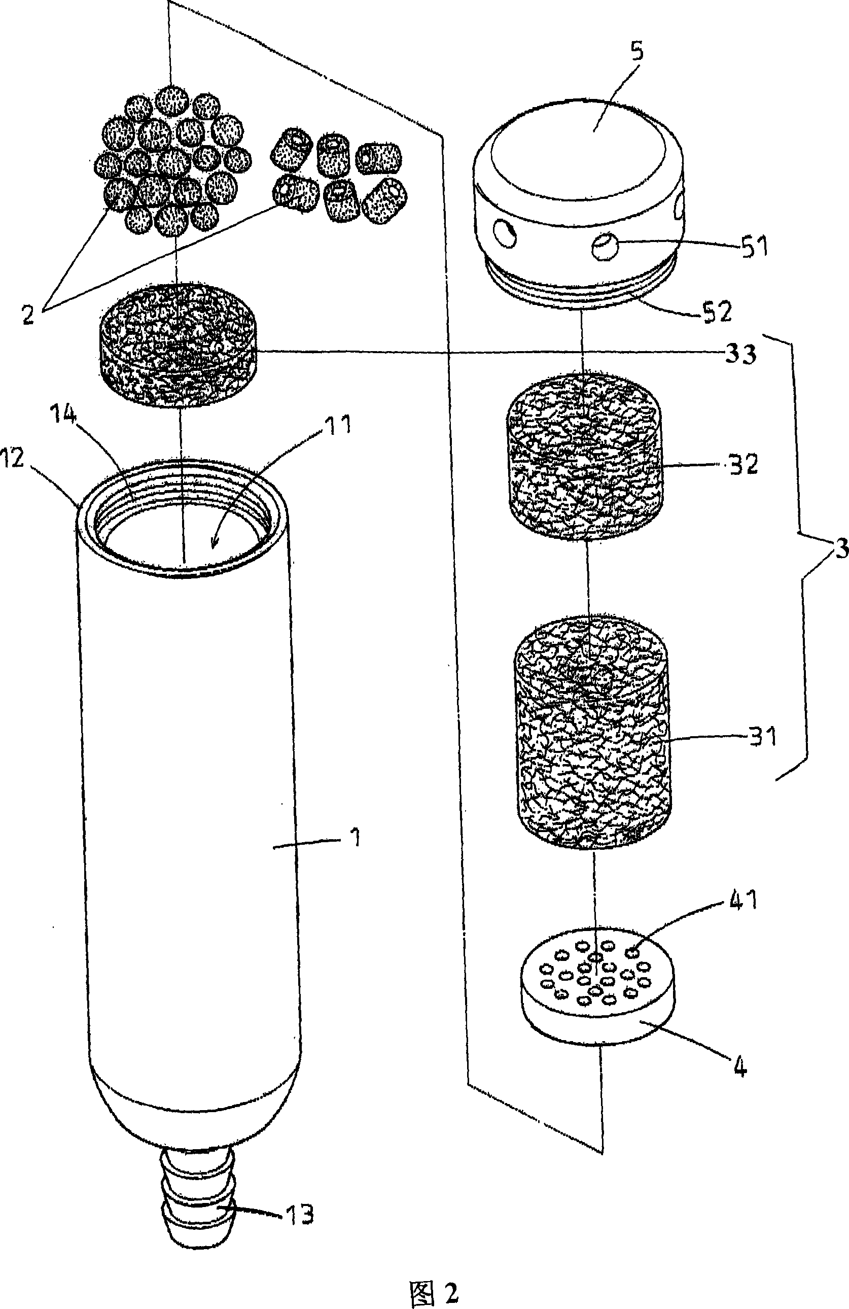
[0027] Please refer to Fig. 2, Fig. 4, Fig. 5, and Fig. 2 and Fig. 5 show that the filter element 3 is arranged in the accommodating space 11 of the main body 1 and the end of the air outlet pipe 13, and more specifically, the filter element 3 is set to be processed with non-woven fabric. The third filter material 33 is shaped like a filter cake, and the end of the accommodating space 11 near the air inlet 12 is provided with the same first and second filter materials 31 shaped like a filter column processed by non-woven fabric. , 32, the first, second, and third filter materials 31, 32, and 33 are used to filter dust particles in the air to purify them. Between the carbonized magnetic particles 2 and the first filter material 31 is provided a ventilation spacer 4 containing a plurality of vent holes 41 for positioning all the carbonized magnetic particles 2 and through air. In this embodiment, two kinds of carbonized magnetic particles 2 of different shapes are given, one is in
Embodiment 3
[0029] Please refer to Fig. 3, in this embodiment, the intake cover 5 recommended by the applicant is different from Embodiment 1, the main difference is that the former cannot control and adjust the intake air volume, while the structure of this example can regulate the intake air volume. Because the thin air is different in the plain area and the plateau area, generally, the structure of the present invention of the air intake cover 5 shown in Fig. 1 and Fig. 2 can be directly adopted in the plain area. As the temperature rises, the intake air volume should be gradually reduced, otherwise it will cause difficulty in starting the car. In view of this, the air intake cover 5 recommended by the present invention carries an adjustment plate 54, which is arranged at the position of the air intake port 12, and the shape can be fan-shaped or can be set on the top surface of the bell-shaped air intake cover 5. Crescent shape or claims banana shape, also can be the air inlet 51 of other
PUM
| Property | Measurement | Unit |
|---|---|---|
| Diameter | aaaaa | aaaaa |
Abstract
Description
Claims
Application Information
 - R&D Engineer
- R&D Manager
- IP Professional
- Industry Leading Data Capabilities
- Powerful AI technology
- Patent DNA Extraction
Browse by: Latest US Patents, China's latest patents, Technical Efficacy Thesaurus, Application Domain, Technology Topic.
© 2024 PatSnap. All rights reserved.Legal|Privacy policy|Modern Slavery Act Transparency Statement|Sitemap