Dual-bottle type water heater

A technology of water heater and double inner tank, applied in the directions of water heater, fluid heater, lighting and heating equipment, etc., can solve the problems of energy waste, inability to obtain hot water, influence of bathing comfort, etc., and achieve the effect of energy saving

Inactive Publication Date: 2007-05-23
李庆祝
View PDF0 Cites 1 Cited by
  • Summary
  • Abstract
  • Description
  • Claims
  • Application Information

AI Technical Summary

Benefits of technology

This patented technology allows an improved dual-tower water heat pump with better performance at lower pressures than traditional systems while also providing more flexibility during use depending on whether it's needed frequently (no tap) or indoor conditions where cold temperatures may affect its efficiency.

Problems solved by technology

The technical problem addressed for this patented technology relates to improving the performance (efficiency) of existing fallwater/pressure-based systems while reducing power consumption compared with other methods such as electrical resistance wire heatings.

Method used


Image

  • Dual-bottle type water heater

Examples


Embodiment Construction

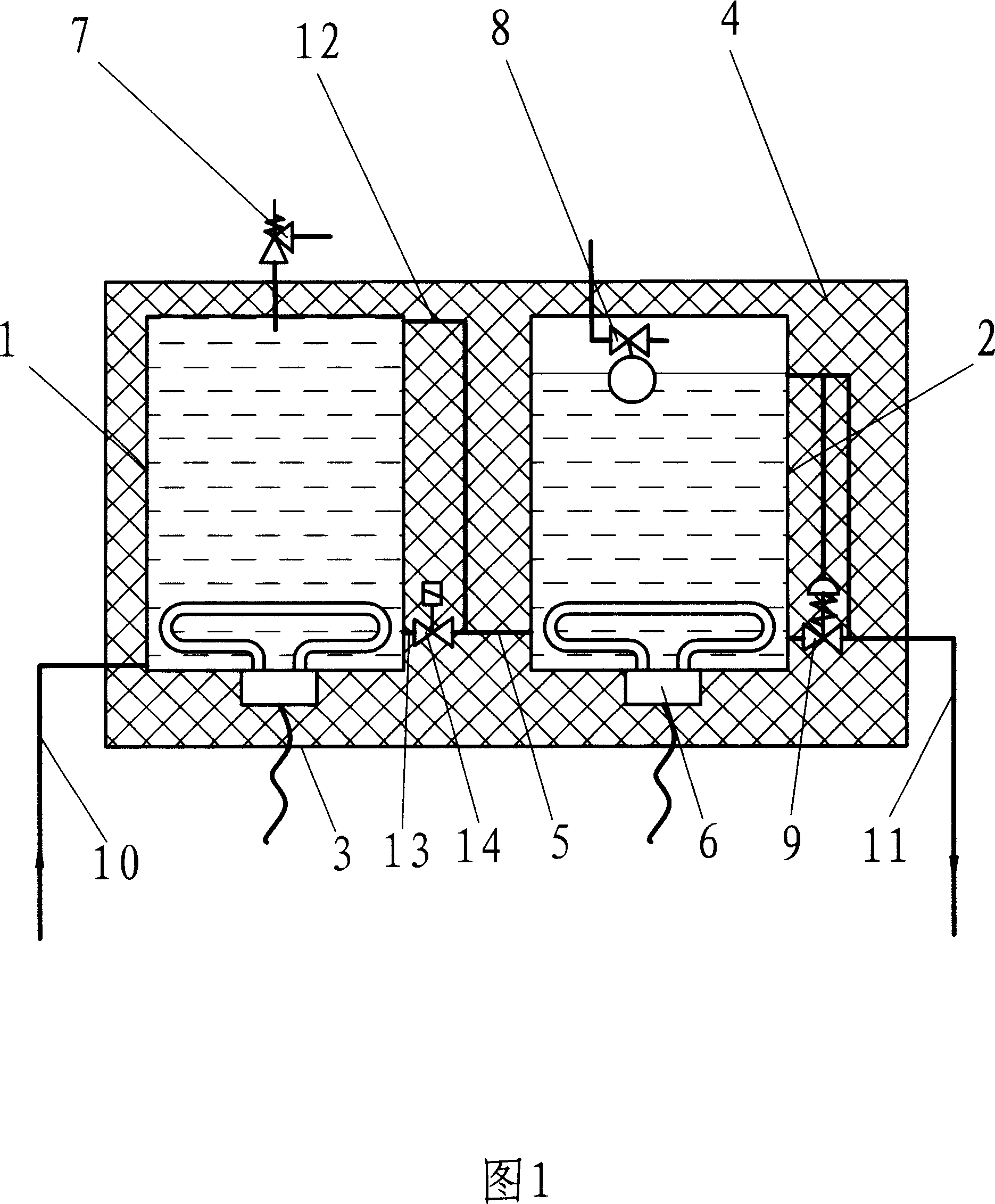
[0009] The specific embodiment shown in Figure 1 is a dual-inner electric water heater for heating by electric energy, which mainly consists of a water inlet inner tank 1, a water outlet inner tank 2, a shell 3, an insulating material 4, a connecting pipe 5, and an electric heater. 6. Safety valve 7, float valve 8, hydraulic control valve 9, upper water pipe 10, lower water pipe 11, upper water outlet pipe 12, lower water outlet pipe 13, water inlet liner 1 and water outlet liner 2 are installed in the shell 3 , between the water inlet inner tank 1 and the water outlet inner tank 2, between the two inner tanks and the outer shell 3 is filled with thermal insulation material 4, the lower parts of the two inner tanks are equipped with electric heaters 6, and the lower part of the water inlet inner tank 1 is fixedly connected The upper water pipe 10, the safety valve 7 and the floating ball valve 8 which plays the role of degassing are respectively installed on the outside and inside


PUM


Abstract

A dual inner container heater mainly comprises water intake and outlet inner containers, housing, heat protective material, connecting channel, heater, safety valve, control valve, upper and bottom water pipes, upper and bottom water discharge joints, with water intake and outlet inner containers inside the housing, both containers having heaters, water intake container connecting with the upper water pipe, inner container having safety valve. It features in the top and bottom of the inner container separately connects with the top and bottom water discharge channel, the inline channel formed by the top and bottom water discharge channels and the bottom water discharge channel, with an inline control valve at the bottom of the water discharging joint. It enjoys comfortable bathing effect with enough tap water and bearing pressure. It can also get hot water through rainspout when the tap water or tap water pressure is not enough, with less hot water left to save energy.

Description


Claims


Application Information

Patent Timeline
Owner 李庆祝
Why Eureka
Try Eureka