BUCK driving circuit
A driving circuit and driving tube technology, which is applied in the direction of electrical components, adjusting electrical variables, instruments, etc., can solve the problem of high price and achieve the effect of low cost
- Summary
- Abstract
- Description
- Claims
- Application Information
AI Technical Summary
Benefits of technology
Problems solved by technology
Method used
Image

Examples
Embodiment Construction
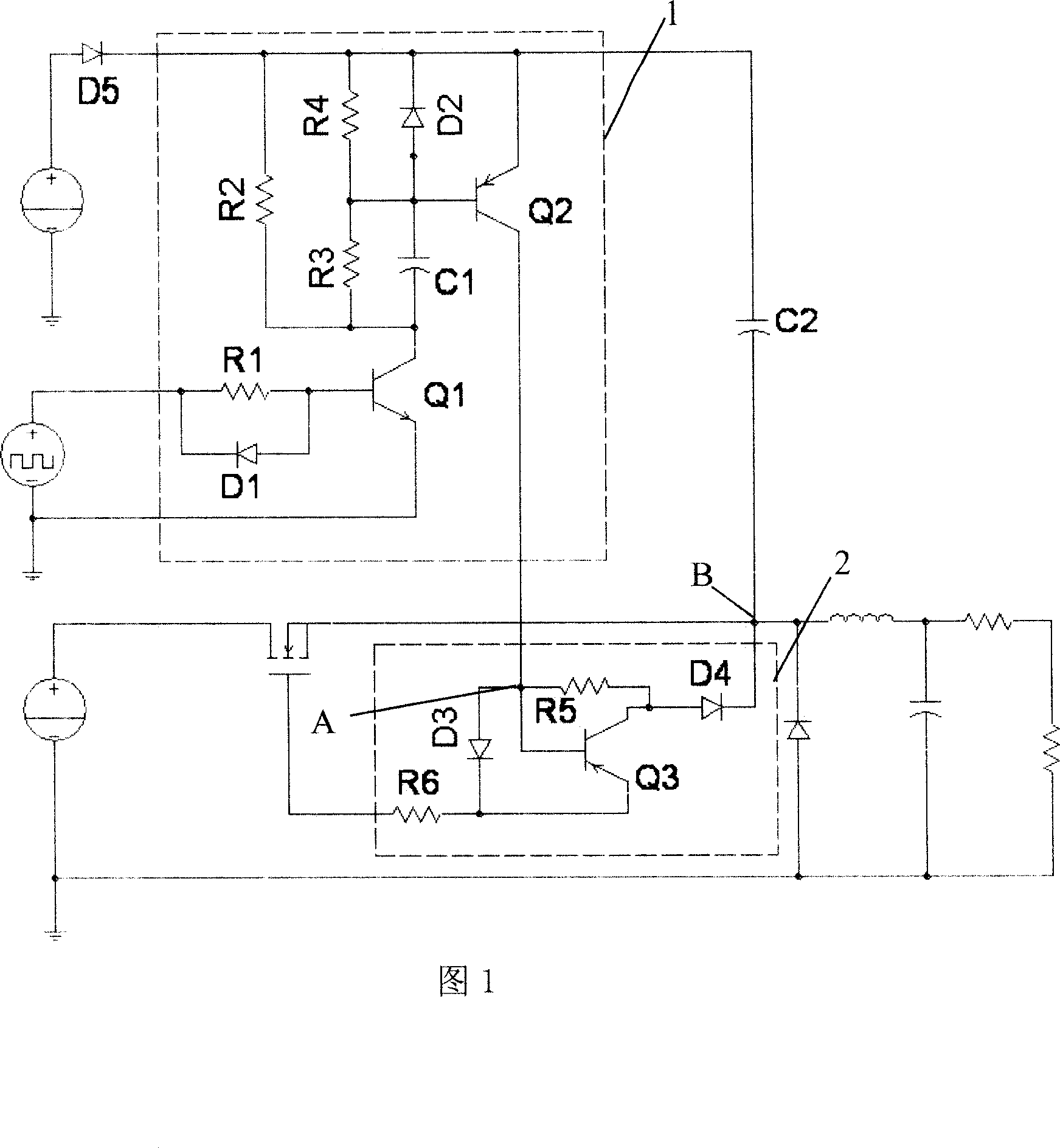
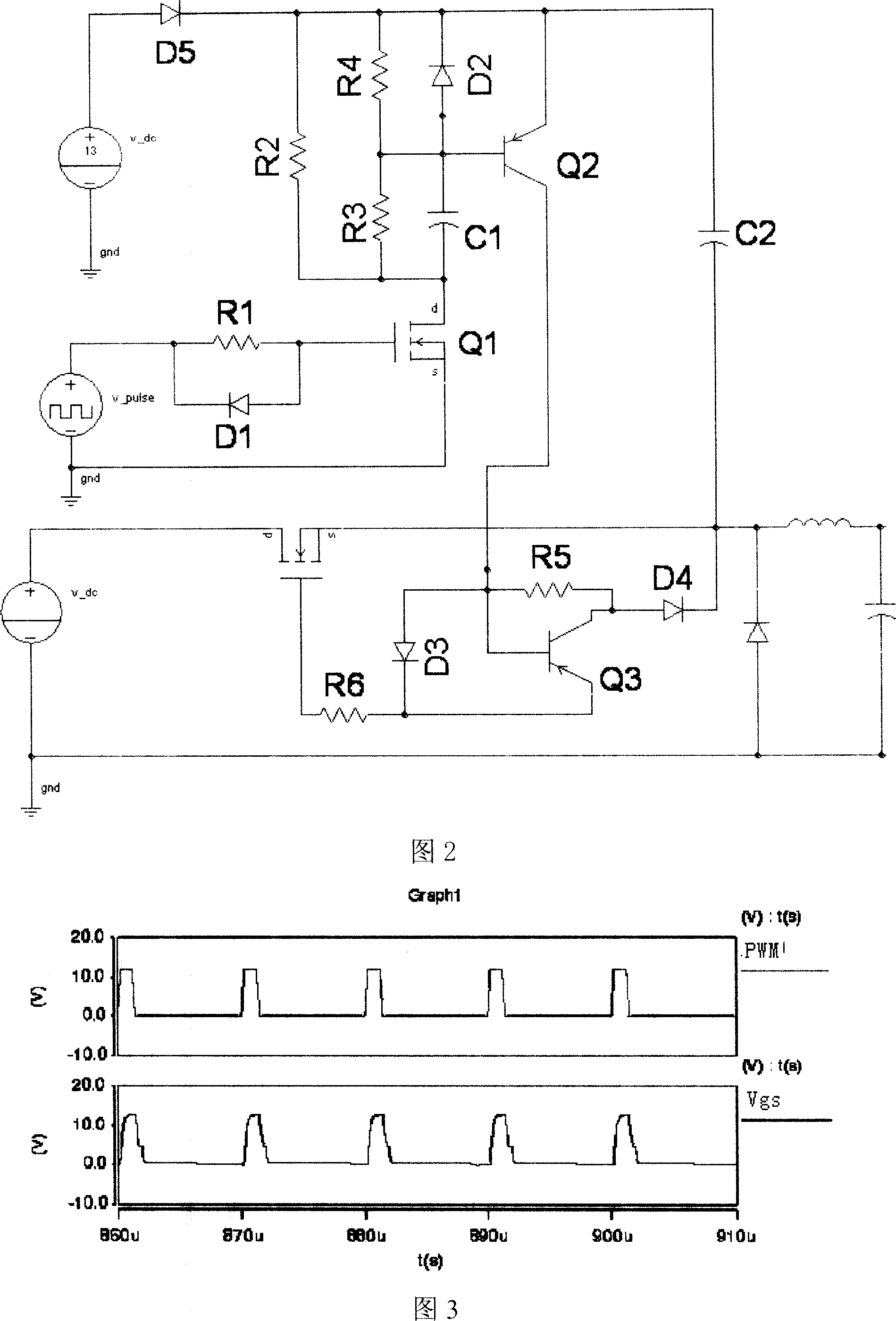
[0021] A specific embodiment of the present invention is shown in FIG. 1 , wherein the first driving transistor Q1 , the second driving transistor Q2 and their peripheral circuits form a rectifier charging circuit 1 . The third drive tube Q3 and its peripheral circuits form the rectifier tube discharge circuit 2 . The drain of the rectifier MOS transistor Q4 is connected to the input voltage terminal VIN, the gate is connected to the emitter of the third driving transistor Q3 through the sixth resistor R6, the source is connected to the second node B, and the second node B is connected to the second node B through the second capacitor C2. The emitters of the two driving transistors Q2 are connected to each other, and are connected to the collector of the third driving transistor Q3 through the fourth diode D4. Wherein, the anode of the fourth diode is connected to the collector of the third driving transistor Q3, and the cathode is connected to the second node B. The second node
PUM
 Abstract
Description
Claims
Application Information
 - R&D Engineer
- R&D Manager
- IP Professional
- Industry Leading Data Capabilities
- Powerful AI technology
- Patent DNA Extraction
Browse by: Latest US Patents, China's latest patents, Technical Efficacy Thesaurus, Application Domain, Technology Topic.
© 2024 PatSnap. All rights reserved.Legal|Privacy policy|Modern Slavery Act Transparency Statement|Sitemap