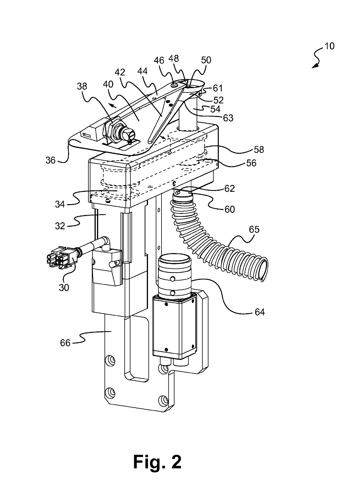
[0007]In an aspect, a lead trimming device, or module, is disclosed. The lead trimming device includes a lead trimmer, a pneumatic actuator coupled to the lead trimmer and a rotation motor assembly coupled to the lead trimmer. The lead trimmer is configured to cut a lead protruding from a component. The pneumatic actuator is configured to actuate the lead trimmer. The rotation motor assembly is configured to rotate the lead trimmer between a plurality of different cutting angles. In some embodiments, the lead protrudes at least partly in a Z-direction and the rotation motor assembly is configured to rotate the lead trimmer in an X-Y plane. In some embodiments, the rotation motor assembly comprises a rotation motor and a drive cam coupled to the rotation motor and to the lead trimmer. In some embodiments, the lead trimmer comprises a bracket having a first end and a second end, the first end coupled to the drive cam. In some embodiments, the second end of the bracket is free floating. In some embodiments, the lead trimmer further comprises a fixed cutting handle fixedly coupled to the bracket and a movable cutting handle movably coupled to the fixed cutting handle at a pivot point. In some embodiments, a first end of the fixed cutting handle and a first end of the movable cutting handle form a cutting head. In some embodiments, a second end of the movable cutting handle is coupled to the pneumatic actuator. In some embodiments, the lead trimming device also includes a trimmed lead collector positioned proximate a cutting end of the lead trimmer, wherein the trimmed lead collector is configured to receive a trimmed portion of the lead cut from the lead by the lead trimmer. In some embodiments, the lead trimming device also includes a vacuum hose coupled to the trimmed lead collector, wherein the vacuum hose is configured to remove the trimmed portion of the lead received by the trimmed lead collector. In some embodiments, the trimmed lead collector comprises a receptacle having a first opening configured to receive the trimmed portion of the lead cut from the lead and a second opening coupled to the vacuum hose.
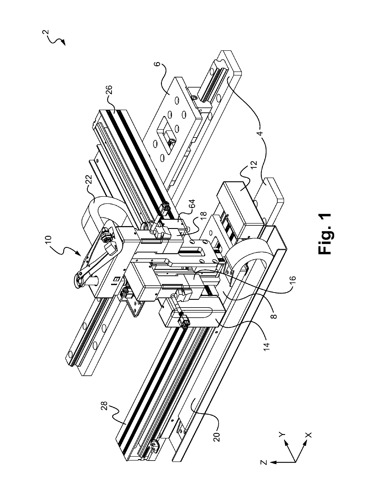
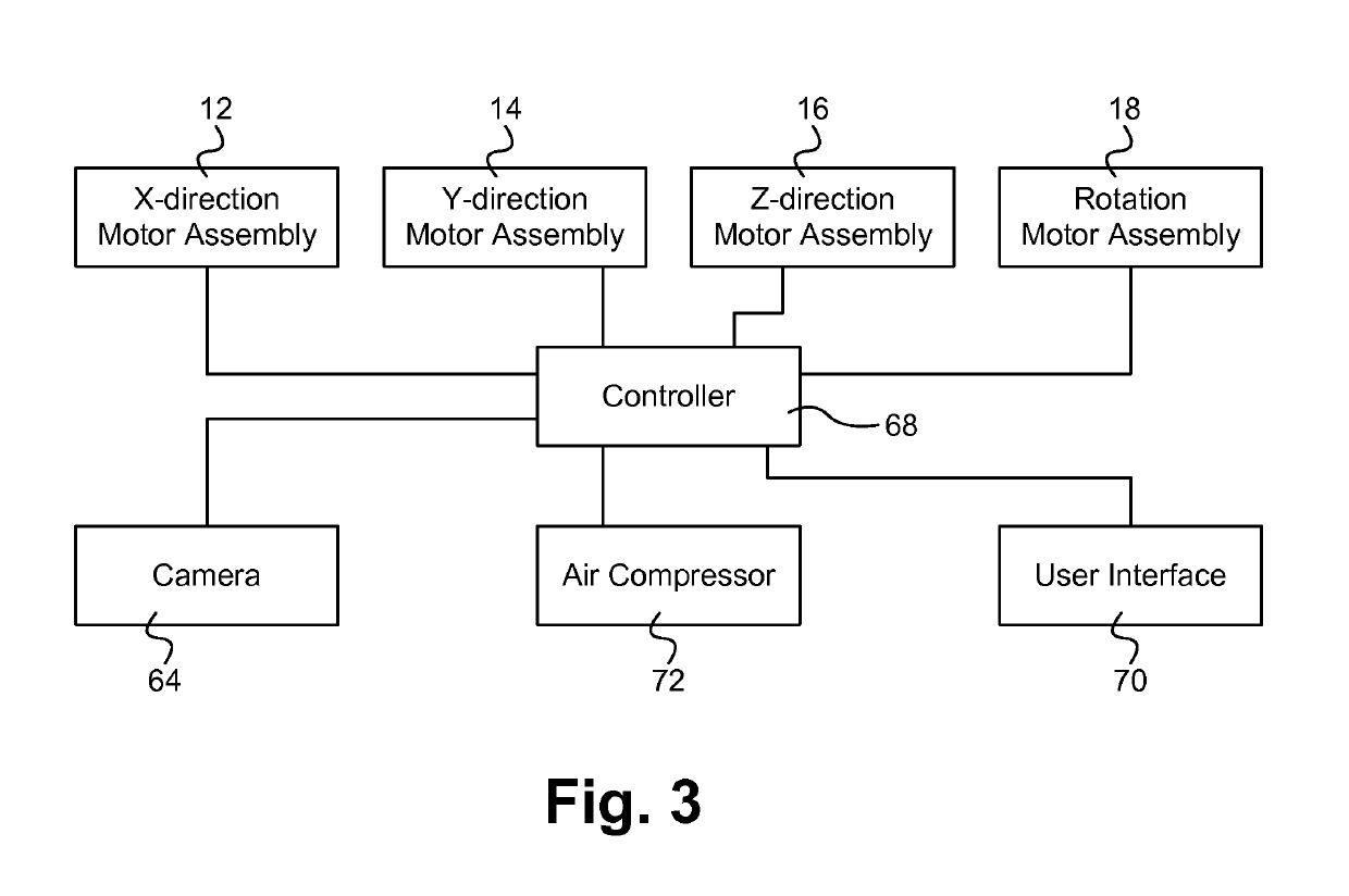
[0008]In another aspect, a system for lead trimming is disclosed. The system includes a component having one or more leads to be trimmed, a gantry robot, a lead trimming device and a control module. The lead trimming device is coupled to the gantry robot. The lead trimming device includes a lead trimmer, a pneumatic actuator coupled to the lead trimmer and a rotation motor assembly coupled to the lead trimmer. The lead trimmer is configured to cut the one or more leads. The pneumatic actuator is configured to actuate the lead trimmer. The rotation motor assembly is configured to rotate the lead trimmer between a plurality of different cutting angles. The control module is coupled to the gantry robot and to the lead trimming device. In some embodiments, the gantry robot comprises an XYZ gantry robot. In some embodiments, the controller is configured to adjust a position of the lead trimmer for different lead length protrusions of the lead from the component. In some embodiments, the controller is coupled to the rotation motor assembly and is configured to control the rotation motor assembly so as to select the cutting angle. In some embodiments, the lead protrudes from the component at least partly in a Z-direction, and the lead trimmer is configured to rotate in an X-Y plane. In some embodiments, the rotation motor assembly comprises a rotation motor and a drive cam coupled to the rotation motor and to the lead trimmer. In some embodiments, the lead trimmer comprises a bracket having a first end and a second end, the first end coupled to the drive cam. In some embodiments, the second end of the bracket is free floating. In some embodiments, the lead trimmer further comprises a fixed cutting handle fixedly coupled to the bracket and a movable cutting handle movably coupled to the fixed cutting handle at a pivot point. In some embodiments, a first end of the fixed cutting handle and a first end of the movable cutting handle form a cutting head. In some embodiments, a second end of the movable cutting handle is coupled to the pneumatic actuator. In some embodiments, the system also includes a trimmed lead collector positioned proximate a cutting end of the lead trimmer, wherein the trimmed lead collector is configured to receive a trimmed portion of the lead cut from the lead by the lead trimmer. In some embodiments, the system also includes a vacuum hose coupled to the trimmed lead collector, wherein the vacuum hose is configured to remove the trimmed portion of the lead received by the trimmed lead collector. In some embodiments, the trimmed lead collector comprises a receptacle having a first opening configured to receive the trimmed portion of the lead cut from the lead and a second opening coupled to the vacuum hose. In some embodiments, the system also includes a camera coupled to the gantry robot.
