Bolt catch engagement/magazine release system

a technology of bolt catch and release system, which is applied in the direction of weapon components, ammunition loading, weapons, etc., to achieve the effects of low manufacturing cost, convenient and efficient manufacturing and marketing, and durable and reliable construction

Active Publication Date: 2020-08-25
CHRISTOPHER LOUIS C +1
View PDF4 Cites 6 Cited by
  • Summary
  • Abstract
  • Description
  • Claims
  • Application Information

AI Technical Summary

Benefits of technology

The technical effect described by this patented inventor relates to improving existing locking mechanisms that use magnetic force or spring pressure to secure objects together without requiring tools like bolts. This makes them more efficient than traditional methods while also being able to quickly assemble and sell these locks at lower costs compared to older solutions. Additionally, there are other benefits associated with the current design of conventional lockings: they have longer lifespan due to their lack of moving parts, less expensive material needed during production, easy assembly, and ease-of-use features.

Problems solved by technology

The technical problem addressed in this patented design relates to improving the safety and convenience associated with existing magazines or cartridges designed into current designs.

Method used


Image

  • Bolt catch engagement/magazine release system
  • Bolt catch engagement/magazine release system
  • Bolt catch engagement/magazine release system

Examples


Embodiment Construction

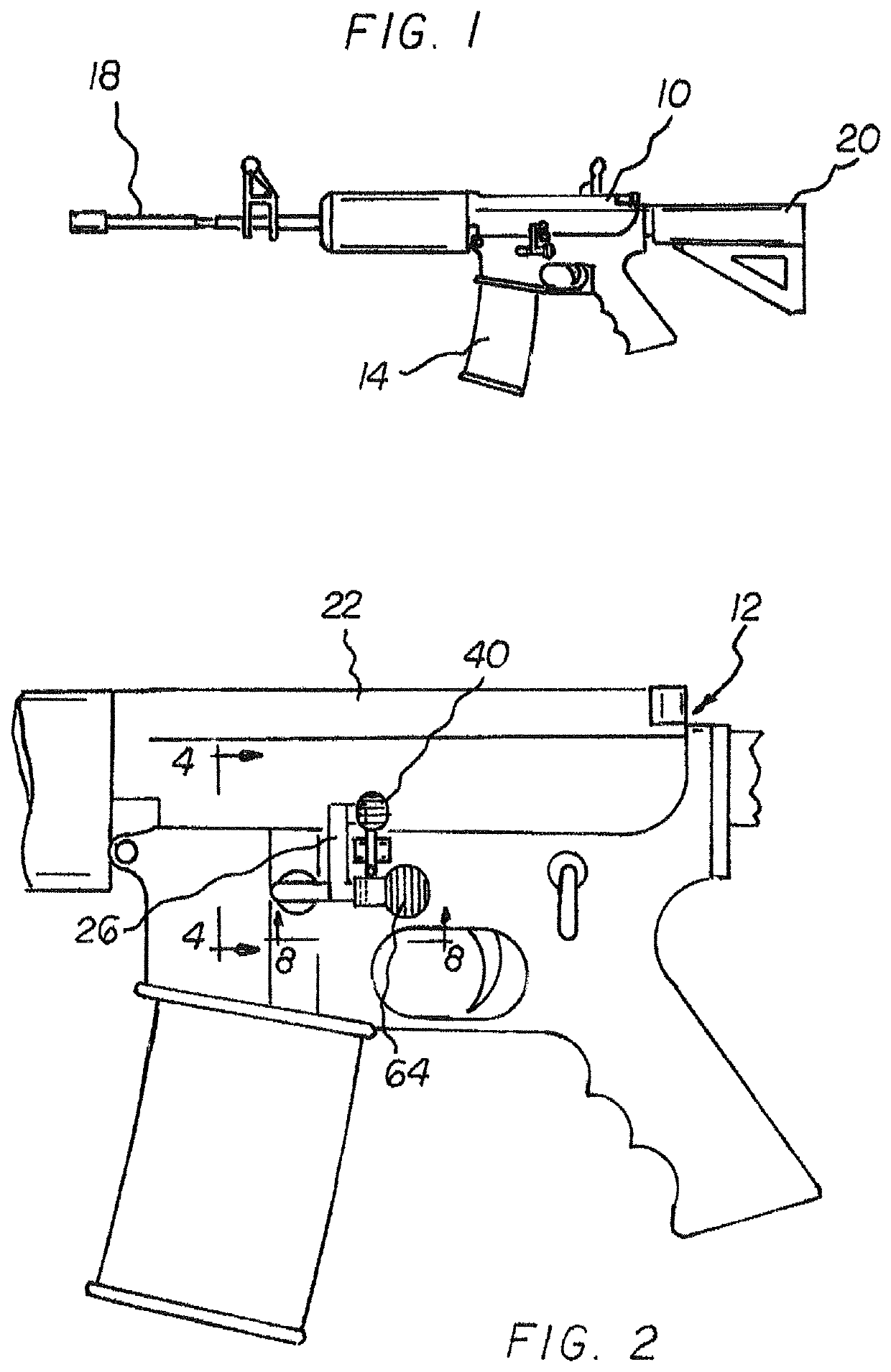
[0032]With reference now to the drawings, and in particular to FIG. 1 thereof, the preferred embodiment of the new and improved bolt catch engagement / magazine release system embodying the principles and concepts of the present invention and generally designated by the reference numeral 10 will be described.

[0033]The present invention, the bolt catch engagement / magazine release system 10 is comprised of a plurality of components. Such components in their broadest context include a firearm and an actuation pin. Such components are individually configured and correlated with respect to each other so as to attain the desired objective.

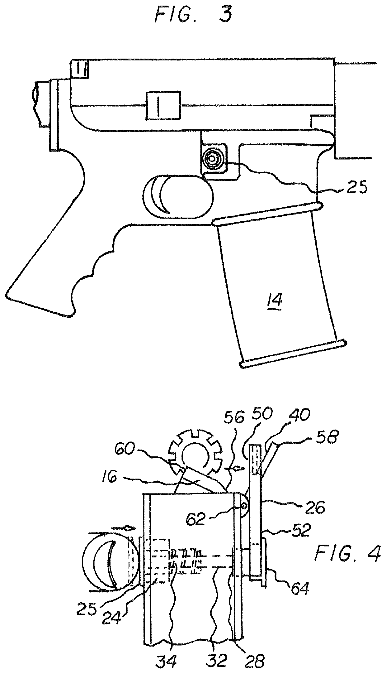
[0034]A rifle 10 with a bolt catch engagement / magazine releasing system 12 is provided. Both releasing a magazine 14 and engaging a bolt catch 16 are done with a single movement. The single movement with the releasing and the engagement is done in a safe, convenient, and convenient manner.

[0035]First provided in the preferred embodiment is the rifle 10.


PUM


Abstract

A firearm has a first side, a second side, a forward section with a barrel, and a rearward section with a stock. The firearm has a central section with an actuation button on the first side and a bolt catch and bolt catch linkage on the second side. A magazine and magazine release are between the actuation button and the bolt catch linkage. An actuation pin extends through the central section from the actuation button to both the bolt catch linkage and the magazine release. A coil spring urges the actuation button outwardly to an inoperative extended orientation. The actuation button is adapted to be depressed for both releasing the magazine and engaging the bolt catch.

Description


Claims


Application Information

Patent Timeline
Owner CHRISTOPHER LOUIS C
Why Eureka
Try Eureka